If you require more than two settings for your measurements, you can either save the individual
settings in the project or export them in *.clg format, and load or import them, if necessary.
You can record individual bits of a parameter (e.g. r0722. 1) by allocating the relevant bit using
"bit track" ( ).
Using the mathematical function ( ) you can define a curve, for example, the difference
between the speed setpoint and the speed actual value.
The device trace shows "individual bits" or "mathematical functions" as signal No. 9.
Recording cycle and duration
The device trace records data in a CU-dependent basic cycle clock. The maximum recording
duration depends on the number of recorded signals and the trace clock cycle.
Proceed as follows to extend the recording duration:
1. Multiply the trace clock cycle by an integral number.
2. Accept the displayed maximum duration using .
Alternatively, you can also specify the measurement period and then calculate the trace clock
cycle of STARTER using .
Trigger (condition to start the device trace)
The device trace starts as soon as you press the (start trace) button.
Using the button , you can define another trigger to start the device trace.
The pretrigger defines the time in which the signals are traced before the trigger condition. As
a consequence, the trigger condition traces itself.
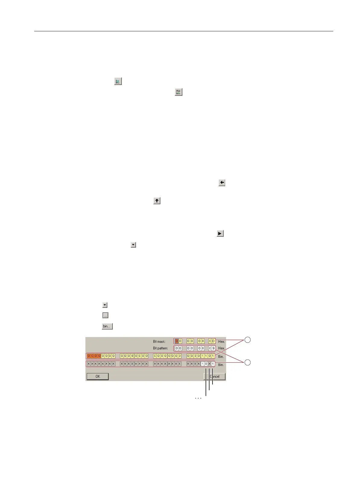
Example of a bit pattern as trigger:
You must define the pattern and value of a bit parameter for the trigger. To do so, proceed as
follows:
Using , select "Trigger to variable - bit pattern"
Using , select the bit parameter
Using , open the screen form in which you set the bits and their values for the start condition
① Select the bits for the trace trigger, upper row hex format, lower row binary format
② Define the bits for the trace trigger, upper row hex format, lower row binary format
Figure A-3 Trigger as bit pattern of r0722 (status of the digital inputs)
Appendix
A.3 The device trace in STARTER
Converter with the CU230P-2 Control Units
Operating Instructions, 09/2017, FW V4.7 SP9, A5E34257946B AE 531

 Loading...


