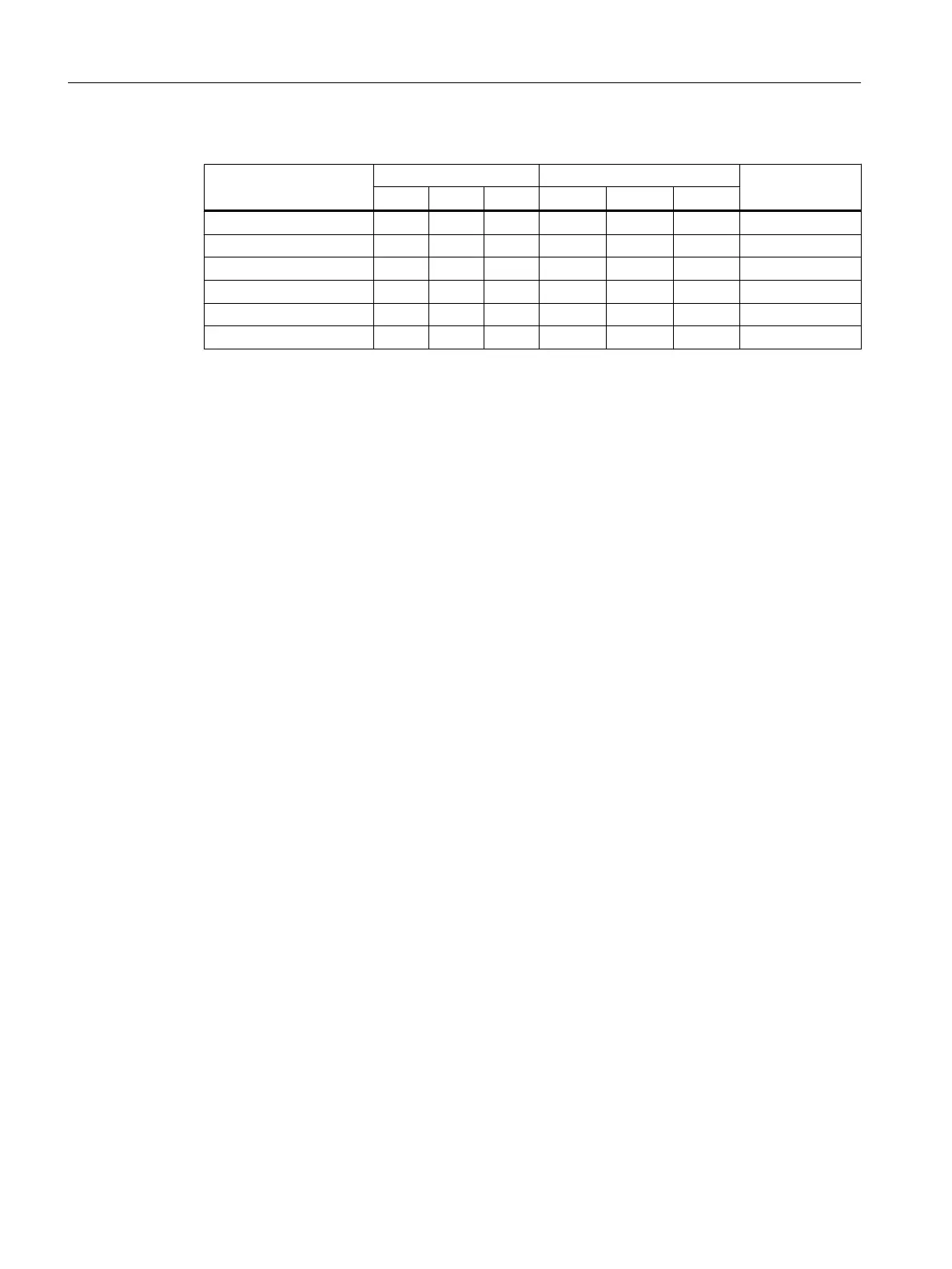
Table 4-19 Drilling dimensions, cooling clearances and fixing
Frame size Drilling dimensions [mm] Cooling air clearances [mm]
1)
Fixing/torque
[Nm]
b h c Top Bottom Front
FSD without filter 235 325 11 300 300 65 4 x M6 / 6
FSD with filter 235 419 11 300 300 65 4 x M6 / 6
FSE without filter 235 405 11 300 300 65 4 x M6 / 6
FSE with filter 235 541 11 300 300 65 4 x M6 / 6
FSF without filter 300 598 11 350 350 65 4 x M8 / 13
FSF with filter 300 898 11 350 350 65 4 x M8 / 13
1)
You can mount the Power Modules without any lateral cooling air clearance. For tolerance reasons,
we recommend a lateral clearance of approx. 1 mm.
Installing
4.3 Installing Power Modules
Converter with the CU230P-2 Control Units
78 Operating Instructions, 09/2017, FW V4.7 SP9, A5E34257946B AE

 Loading...


