Wiring
4-23
ET 200X Distributed I/O Device
EWA 4NEB 780601602-06
Wiring of M12 coupler plug for digital inputs
To connect the digital inputs, you require:
A 5-pin, M12 coupler plug, possibly integrally molded
A flexible 3-, 4- or 5-core copper cable with a core cross-section of 0.75 mm
2
Wire the coupler plug in accordance with the pinout table below. The pinout of the
sockets X1 to X4/X8, which are used for the inputs on the ET 200X, is shown
together with the data for the individual modules in Section 7.1 ff.
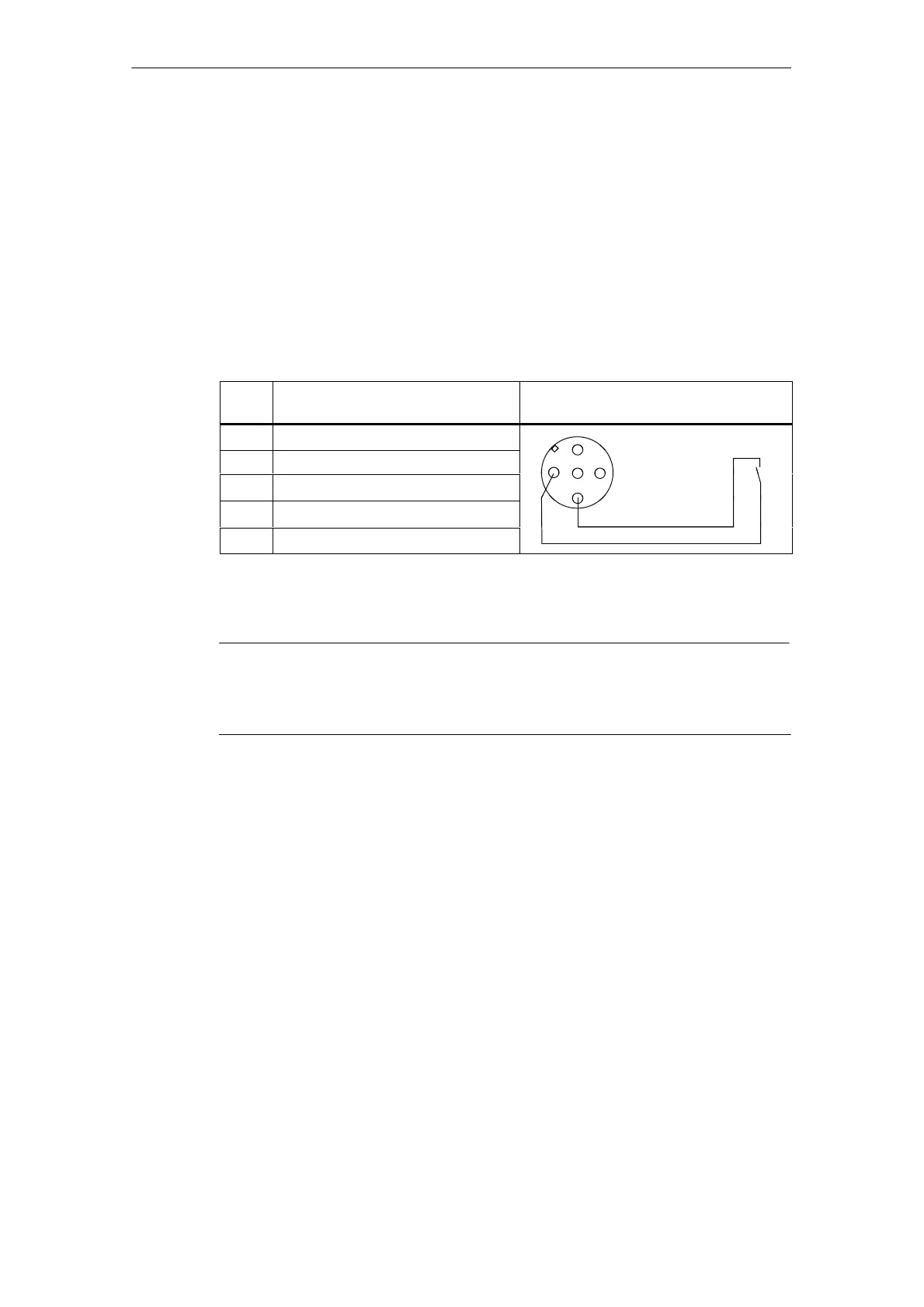
Table 4-5 Pinout of the coupler plug for digital inputs
Pin
Assignment View of coupler plug
(wiring side)
1 24 V power supply for sensor*
2** Input signal
2
3 Chassis ground, power supply
13
5
4 Input signal
4
5 PE
* Made available by the ET 200X for the connected sensor
** Only relevant if socket has 2 assigned channels
Note
If a sensor has a normally-closed contact and a normally-open contact, the
normally-closed contact is automatically wired to pin 2. The channel assigned to
pin 2 can thus no longer be used for the adjacent socket.
Wiring of M12 coupler plug for digital inputs (DESINA/ECOFAST)
To connect the digital inputs, you require:
A 5-pin, M12 coupler plug, possibly integrally molded
A flexible 4- or 5-core copper cable with a core cross-section of 0.75 mm
2
Wire the coupler plug in accordance with the pinout table below. The pinout of
sockets X1 to X8, which are used for the inputs on the
ET 200X-DESINA/ECOFAST, is shown together with the data for the individual
modules in Section 7.5 ff.
Connecting digital inputs (DESINA):
You have set the following parameters:
Pin 2 as diagnostic input and pin 4 as digital input.
Channel type (pin 4): digital input
Input functionality (pin 2): diagnostic input