Technical Specifications
7-106
ET 200X Distributed I/O Device
EWA 4NEB 780601602-06
7.21.7 Connecting measuring sensors to the analog inputs
You can connect different measuring sensors to the analog inputs depending on
the type of measurement involved:
Voltage sensors
Current sensors as:
– Two-wire measuring transducers
– Four-wire measuring transducers
Resistance thermometers
Abbreviations used
The following abbreviations are used in the figures in this section:
I
C+
: Constant-current line (positive)
I
C–
: Constant-current line (negative)
M
+
: Measuring line (positive)
M
–
: Measuring line (negative)
1M: Frame connection for sensor
1L
+
: Supply voltage connection for DC 24 V sensor
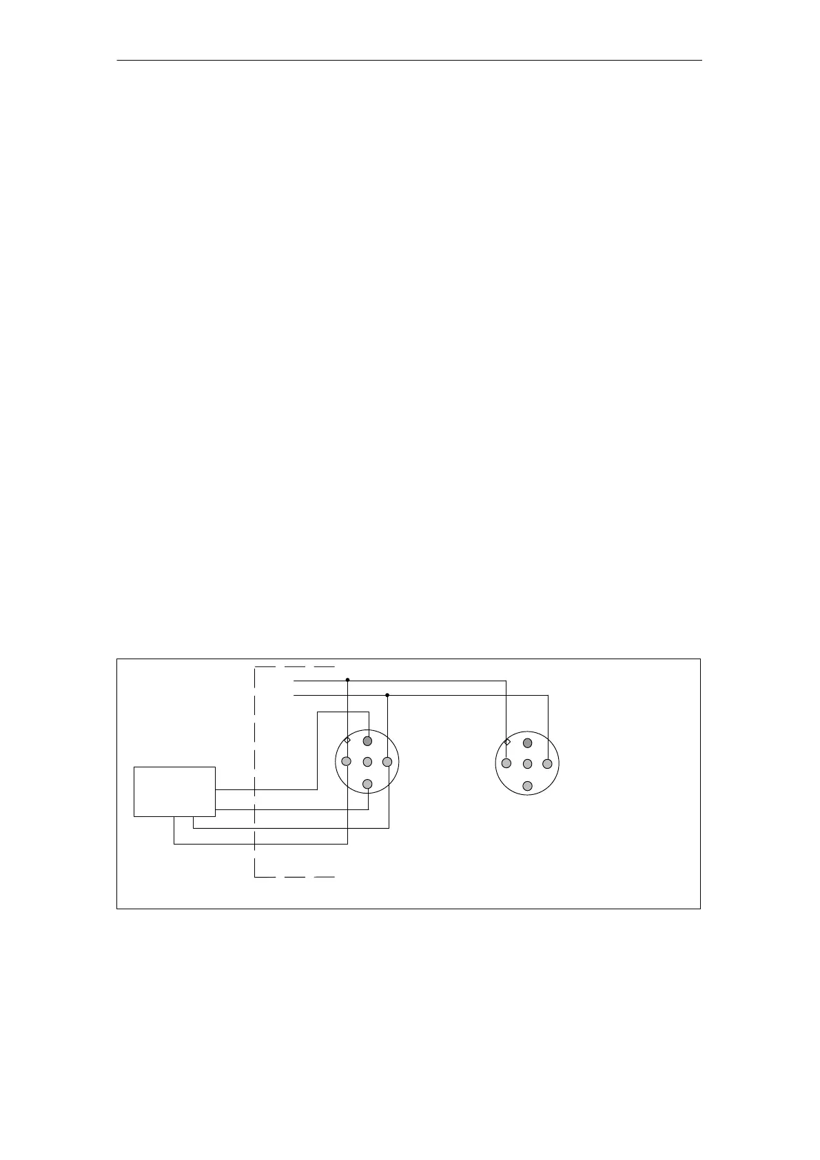
Connecting voltage sensors
The figure below shows how voltage sensors are connected to an expansion
module with analog inputs.
M+
M–
Socket X1
Socket X2
* Made available by the ET 200X for the connected sensor
L+
1M
Connection of socket X2:
see socket X1
Voltage
sensor
+
–
1M*
1L+*
1
2
3
4
1
2
3
4
Figure 7-24 Connection of voltage sensors to analog inputs (EM with order number
6ES7 144-1FB31-0XB0)