Technical Specifications
7-13
ET 200X Distributed I/O Device
EWA 4NEB 780601602-06
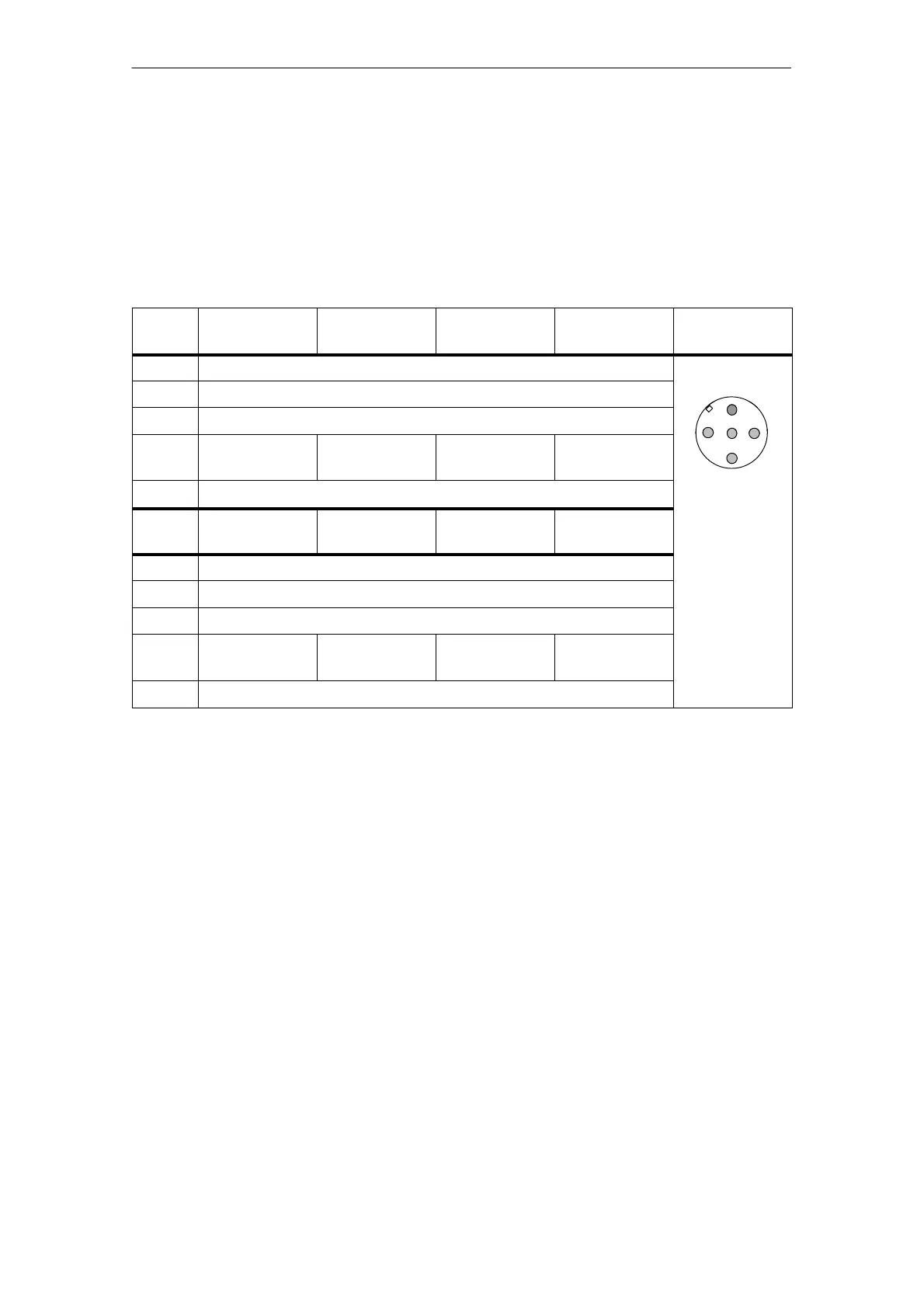
Pinout of the sockets for DI
The following table shows the pinout of the eight sockets used to connect the
digital inputs. You can find the wiring of the connector in the ET 200X manual,
Section 4.4.4. You can find the layout of the sockets in the ET 200X manual,
Appendix C.
Table 7-5 Pinout of sockets X1 to X8 for digital inputs
Pin Assignment
of socket X1
Assignment
of socket X2
Assignment
of socket X3
Assignment
of socket X4
Front view of
socket
1 Sensor supply output 1L+
2 not assigned
3 Chassis ground, power supply
2
4 Input signal,
channel 0
Input signal,
channel 1
Input signal,
channel 2
Input signal,
channel 3
1
3
4
5
5 PE
Pin Assignment
of socket X5
Assignment
of socket X6
Assignment
of socket X7
Assignment
of socket X8
1 Sensor supply output 1L+
2 not assigned
3 Chassis ground, power supply
4 Input signal,
channel 4
Input signal,
channel 5
Input signal,
channel 6
Input signal,
channel 7
5 PE
Covering up unused connections
You must seal off any connections which are not required with M12 screw caps, in
order to ensure that the degree of protection (IP 65, IP 66 or IP 67) is achieved.