Wiring
4-30
ET 200X Distributed I/O Device
EWA 4NEB 780601602-06
4.4.5 Connecting the protective ground to the basic module
Protective ground connection
You must connect the protective ground to the basic module. A grounding screw is
provided on the basic module for this purpose.
Minimum cross-section from the conductor to the protective ground: 4 mm
2
.
The connection to the protective ground is also required to divert the interference
currents and for EMC resistance. To improve the EMC performance, it is advisable
to select the largest possible cross-section for the wire to the protective ground
(e.g. copper braided cable).
Note
Make sure that the protective ground connection always has a low impedance.
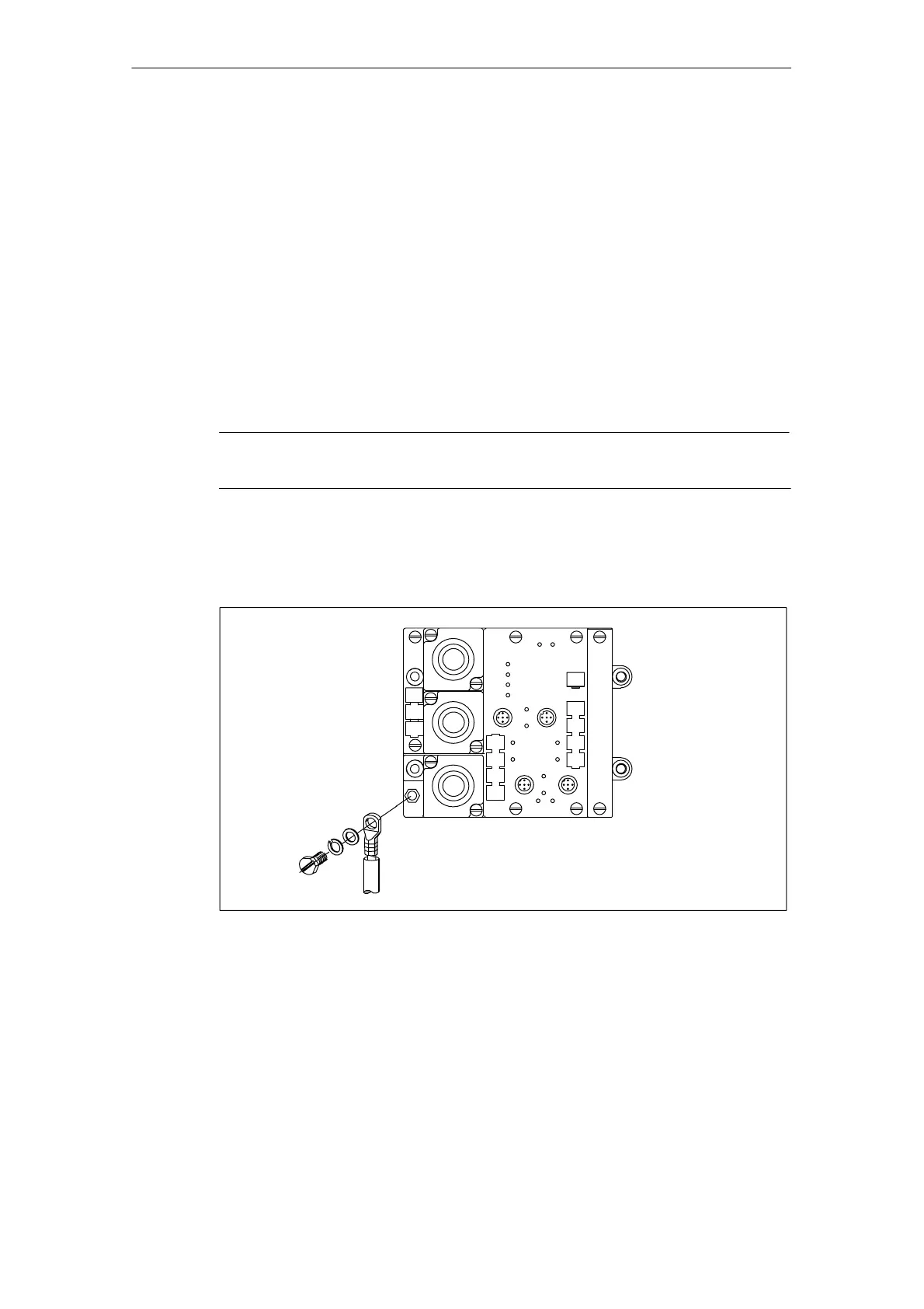
Figure 4-16 shows how the protective ground connects to the BM 141, BM 142
and BM 147/CPU basic modules. The fixing screw M5 is enclosed with the basic
module as standard.
Figure 4-16 Connecting the protective ground to the BM 141, 142 and 147/CPU basic
modules