Dimesioned Drawings and Pinouts
C-15
ET 200X Distributed I/O Device
EWA 4NEB 780601602-06
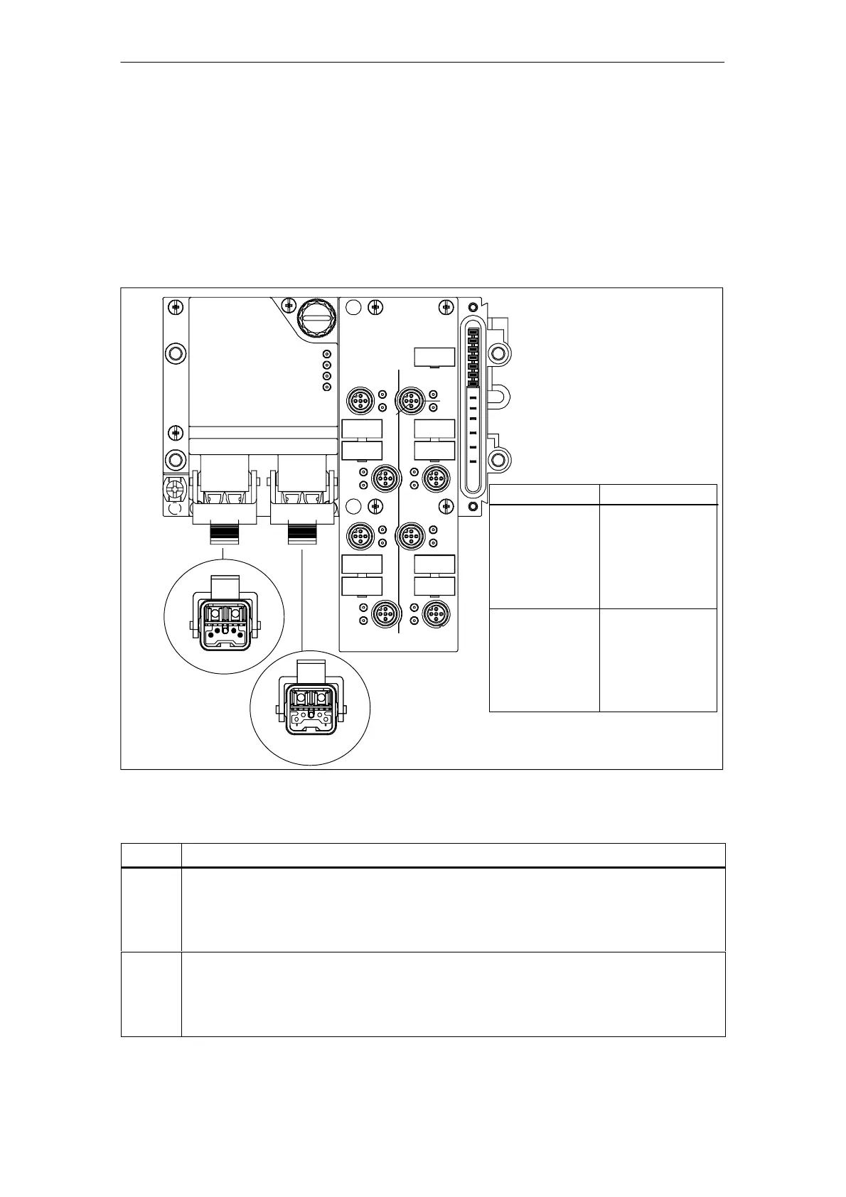
C.10 Pinout of the ET 200X-DESINA
Figure C-13 shows you the pinout of the ET 200X-DESINA using the example of
the BM 143-DESINA FO basic module.
The BM 143-DESINA RS485 basic module has the same pinout on the
PROFIBUS-DP connection (pins 5 and 6) but has copper conductors instead of
fiber-optic cables. The arrangement of sockets X1 to X8 is identical for all DESINA
basic and expansion modules with digital inputs and outputs.
X01 X02
X1
X3
X5
X7
X2
X4
X6
X8
1
2
3
4
5
View of DESINA
connections
(fiber-optic cables)
Supply
Looping through
5
2
1
6
3
4
5
2
1
6
3
4
Socket
X01
Supply
(Supply voltage
for electronics/
sensors, actuators
PROFIBUS-DP)
Pinout
1 L+ (NS*)
2 M (NS*)
3 M (S**)
4 L+ (S**)
5 Signal A (RD***)
6 Signal B (TD***)
X02
Loop through
1 L+ (NS*)
2 M (NS*)
3 M (S**)
4 L+ (S**)
5 Signal A (RD***)
6 Signal B (TD***)
* Non-switched supply voltage
** Switched load voltage
*** on the basis of the DESINA specification
Figure C-13 Pinout of the ET 200X-DESINA
Socket
Pinout of the 8-channel DI/DO
X1
X3
X5
X7
1 Sensor supply output L+ (NS)
2 Diagnostic input or input with NC function.
3 Grounding supply voltage
4 Digital input or output (DESINA) channels 0, 2, 4 and 6
5 not assigned
X2
X4
X6
X8
1 Sensor supply output L+ (NS)
2 Diagnostic input or input with NC function.
3 Grounding supply voltage
4 Digital input or output (DESINA) channels 1, 3, 5 and 7
5 not assigned
 Loading...


