Dimesioned Drawings and Pinouts
C-12
ET 200X Distributed I/O Device
EWA 4NEB 780601602-06
C.8 Pinout of the ET 200X
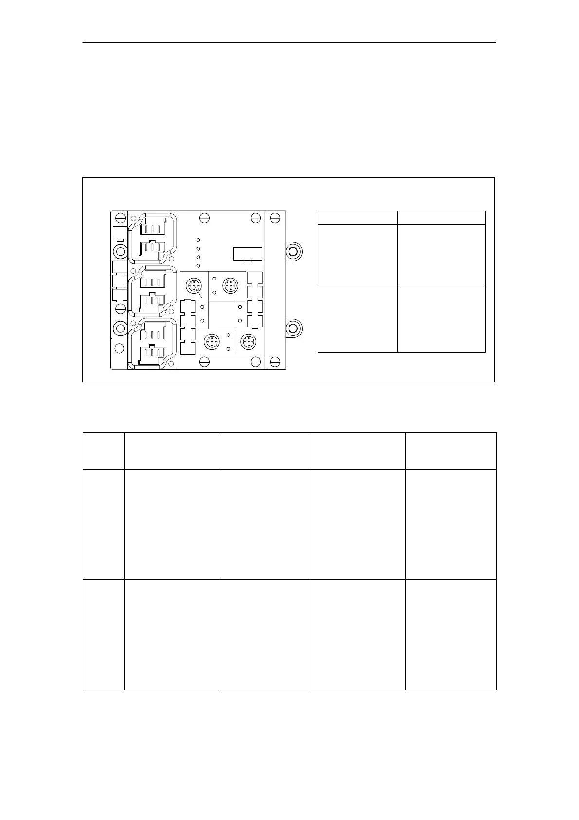
Figure C-11 below shows the pinout of the ET 200X on a BM 141, BM 142,
BM 147/CPU basic module. The arrangement of sockets X1 to X4 is the same on
all basic and expansion modules (BM 141, BM 142, EM 141, EM 142, EM 144,
EM 145) with digital inputs and outputs.
1
2
3
4
5
654
32
1
X1
X2
X3
X4
654
654
32
1
32
1
X01
X02
X03
Basic module
Socket
X01 and X10
(supply voltage
for electronic com-
ponents/sensors,
PROFIBUS-DP)
Pinout
1 B signal
2PE
3 PE/–*
4 A signal
5L+
6M
X03
(load voltage)
1PE
2L+
3M
4PE
5L+
6M
* BM 141/142: PE
BM 147/CPU: not assigned
Figure C-11 Pinout of the ET 200X (BM 141, BM 142, BM 147/CPU)
Socket Pinout of
8-channel DI
Pinout of
4-channel DI
Pinout of
4-channel DO
Pinout of
pneumatic module
(4-channel DI)
X1 1 Sensor supply
output L+
2 Input signal,
channel 4
3 Grounding
supply voltage
4 Input signal,
channel 0
5PE
1 Sensor supply
output L+
2 Input signal,
channel 1
3 Grounding
supply voltage
4 Input signal,
channel 0
5PE
1 –
2 Output signal,
channel 1
3 Grounding
Load current power
supply
4 Output signal,
channel 0
5PE
1 Sensor supply
output L+
2 Input signal,
channel 1
3 Grounding
supply voltage
4 Input signal,
channel 0
5PE
X2 1 Sensor supply
output L+
2 Input signal,
channel 5
3 Grounding
supply voltage
4 Input signal,
channel 1
5PE
1 Sensor supply
output L+
2 –
3 Grounding
supply voltage
4 Input signal,
channel 1
5PE
1 –
2 –
3 Grounding
Load current power
supply
4 Output signal,
channel 1
5PE
1 Sensor supply
output L+
2 Input signal,
channel 3
3 Grounding
supply voltage
4 Input signal,
channel 2
5PE