Installation
3-20
ET 200X Distributed I/O Device
EWA 4NEB 780601602-06
3.4 Terminating PROFIBUS with a terminating resistor
Purpose of the terminating resistor
A bus cable must be connected at both ends (i.e. at the first and last node in the
network) with its characteristic impedance.
Note
The terminating resistor is only necessary with copper conductors with an RS-optic
cables (FO).
Because the BM 143–DESINA FO basic module is connected to the PROFIBUS–DP
by means of fiber-optic cables there is no terminating resistor there.
How to proceed with the ET 200X
In the case of the ET 200X you switch the terminating resistor using two DIP
switches. The two DIP switches are inside the basic module of the ET 200X, under
the connector plate for the connector for PROFIBUS-DP and the supply voltage for
electronic components/sensors.
1. Remove the connector plate from the basic module before you connect the
terminating resistor. The DIL switches are concealed by the connector plate.
2. Connect the terminating resistor using the DIL switches.
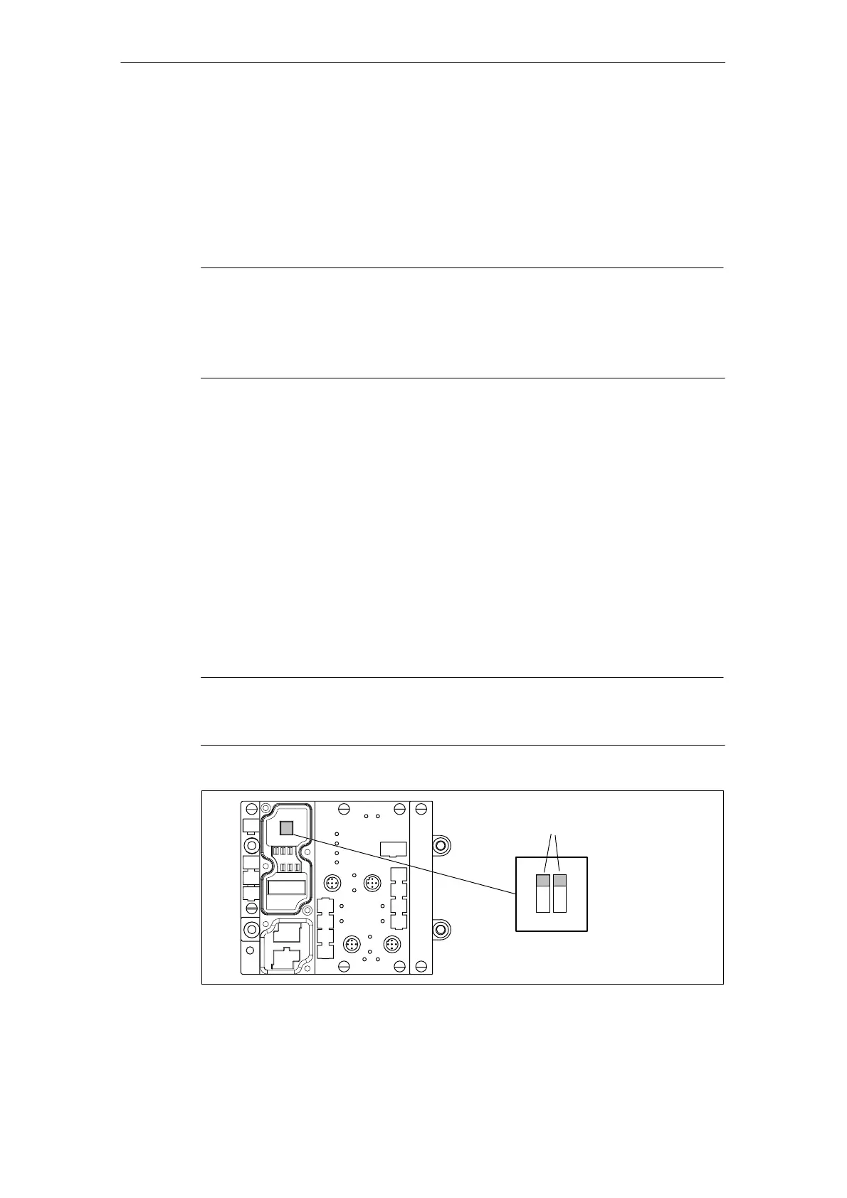
The diagram below shows the location of the DIL switches in the basic module as
well as an example of the switch settings.
Note
The terminating resistor will not function correctly unless both DIP switches of the
terminating resistor are set to ”on” or ”off”.
Example:
terminating resistor
connected
off
on
Figure 3-14 Connecting the terminating resistor