Dimesioned Drawings and Pinouts
C-17
ET 200X Distributed I/O Device
EWA 4NEB 780601602-06
C.12 Pinout of analog inputs/outputs
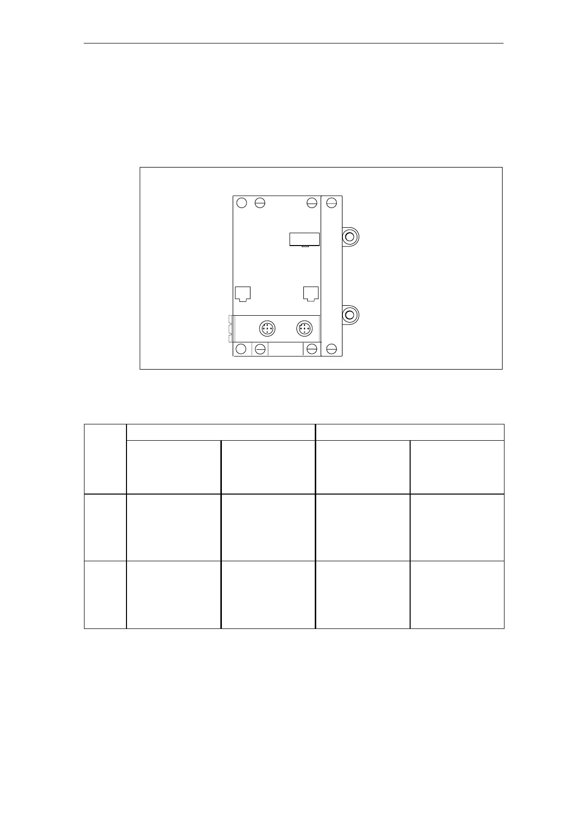
Figure C-15 below shows the pinout of the inputs/outputs of the ET 200X on an
expansion module. The arrangement of the sockets is identical for all expansion
modules with analog inputs and outputs.
1
2
3
X1
X2
Expansion module with analog inputs/outputs
4
Figure C-15 Pinout of expansion module with analog inputs/outputs
Socket Pinout of 2-channel AI Pinout of 2-channel AO
Voltage/current Current Voltage Current
10 V
20 mA
Pt 100
4 to 20 mA 10 V 20 mA
4 to 20 mA
X1 1L+
2 Channel 0 (+)
3 Ground power
supply
4 Channel 0 (–)
1 L+; channel 0 (+)
2 Channel 0 (–)
3 Ground power
supply
4 –
1 Qv channel 0
2 –
3 Ground power
supply
4 –
1 QI channel 0
2 –
3 Ground power
supply
4 –
X2 1L+
2 Channel 1 (+)
3 Ground power
supply
4 Channel 1 (–)
1 L+; channel 1 (+)
2 Channel 1 (–)
3 Ground power
supply
4 –
1 Qv channel 1
2 –
3 Ground power
supply
4 –
1 QI channel 1
2 –
3 Ground power
supply
4 –