Technical Specifications
7-121
ET 200X Distributed I/O Device
EWA 4NEB 780601602-06
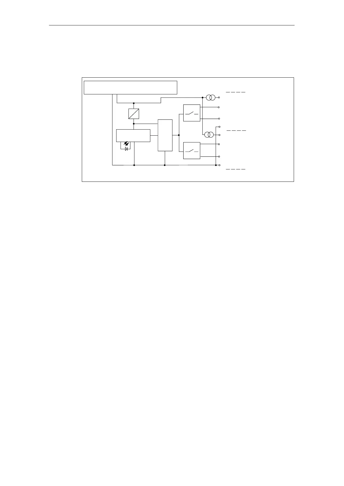
Basic circuit diagram
The basic circuit diagram of the expansion module is shown below.
Socket connections (see Table 7-65)
ADC
So. X1
1L+
1M
Supply voltage for electronic components
and sensors via backplane bus
Backplane bus
interface
So. X2
1
2
3
4
2
4
24 V
5 V
3
1
SF
Figure 7-33 Basic circuit diagram of expansion module EM 144 AI 2 x RTD
Covering up unused connections
You must seal off any connections which are not required with M12 screw caps, in
order to ensure that the degree of protection (IP 65, IP 66 or IP 67) is achieved.



 To Next Page