Configuration Options
2-9
ET 200X Distributed I/O Device
EWA 4NEB 780601602-06
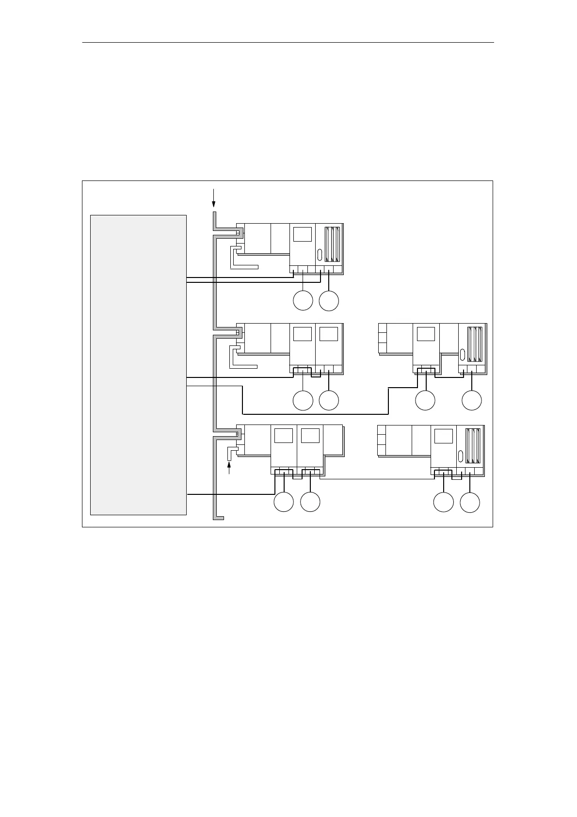
Configuration example
The diagram below shows you three possible configurations with connections for
the 400 VAC load supply voltage, the load and looping through. The possible
configurations for motor starters and frequency converters are the same. You must
take into account that the frequency converters have to be positioned to the right of
the motor starters.
Load voltage
supply
BM
EM
Switch cabinet for power
distribution
MS
EM-
FC
M
3
M
3
BM
EM
MS
MS
M
3
M
3
BM
MS
M
3
BM
EM
MS
M
3
M
3
BM
EM
MS
M
3
M
3
Fed separately to
each motor starter/
frequency converter
Fed separately
to each ET 200X
Fed to the
1st motor starter
M
3
Supply voltage + PROFIBUS-DP looped
through
EM
EM-
FC
EM-
FC
MS
Figure 2-6 Connecting and looping through the load supply voltage
Cables
Please refer to Section 4.4 for a list of suitable cable types.