Installation
3-9
ET 200X Distributed I/O Device
EWA 4NEB 780601602-06
Dimensioned drawing for fixing holes
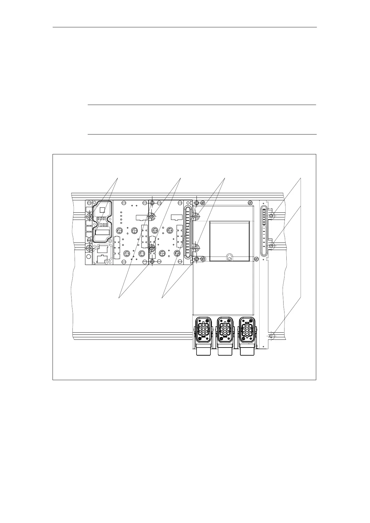
The diagrams below show you the positions of the fixing screw holes for one basic
module, one expansion module and one motor starter or frequency converter. Use
the specified screws.
Note
The ET 200X must be installed on the rail, and screws must be affixed at all the
fixing points.
M5 20M5 20M5 20 M5 20
Rail
M3.5 20 M3.5 20
Figure 3-5 Fixing screws for basic and expansion modules