Commissioning and Diagnostics
5-44
ET 200X Distributed I/O Device
EWA 4NEB 780601602-06
Alarms
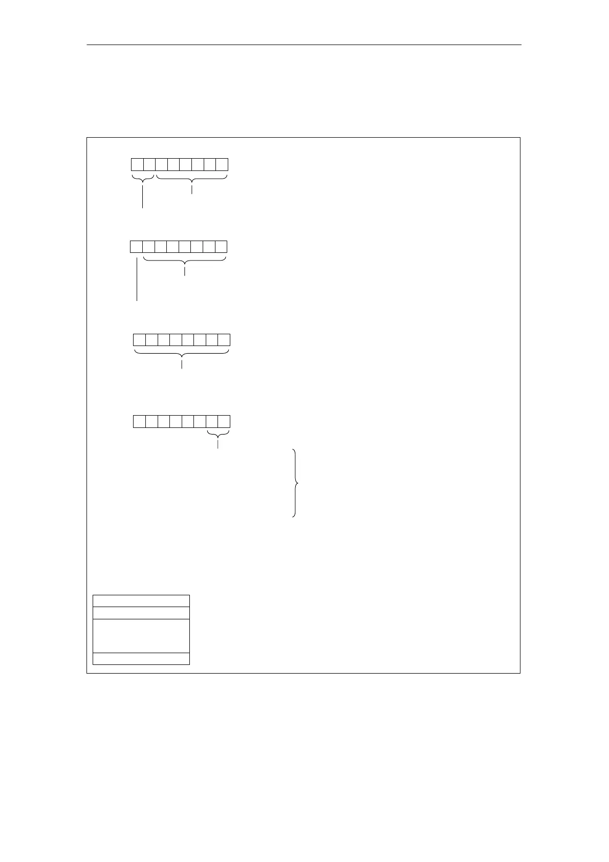
The alarm unit for ET 200X is configured as follows.
Byte x
70
Bit no.
Length of the interrupt section including byte x (= max. 20 bytes)
Code for device-specific diagnosis
00
Byte x+1
70
00
Byte x+2
70
01
70
01
00
B
: Hardware
interrupt
01
B
: At least one
fault is present
10
B
: Going error
11
B
: Reserved
Byte x+3
0000001
B
: Diagnostic interrupt
0000010
B
: Hardware interrupt
Type of interrupt:
04 to 11: Slot of the module that is producing an interrupt
02: BM provides the alarm
6
5
13
6
0
Code for interrupt
”Slot” number
Bytes x+4 to ...
Diagnostic-interrupt data
(contents of data records 0 and 1)
(see Figures 5-14 to 5-17)
.
.
.
Hardware interrupt data
(see Figure 5-18)
... Byte x+19 ... Byte x+7
for
BM 141 (6ES7 141-1BF11-0XB0)
BM 141DI 8 x DC 24V
ECOFAST (6ES7 141-1BF01-0AB0)
BM 141 DI 8 x DC 24V (6ES7 141-1BF40-0AB0)
ECOFAST DIAG
BM 142 (6ES7 142-1BD21-0XB0)
BM 143-DESINA FO (6ES7 143-1BF00-0XB0)
BM 143-DESINA RS485 (6ES7 143-1BF00-0AB0)
00
B
: for
BM 141 (6ES7 141-1BF01-0XB0)
BM 142 (6ES7 142-1BD11-0XB0)
Figure 5-12 Structure of the ET 200X alarm unit
 Loading...


