Commissioning and Diagnostics
5-51
ET 200X Distributed I/O Device
EWA 4NEB 780601602-06
Byte x+4 to x+7 (x+10) for diagnosis of ET 200X
If byte x+2 contains the slot number 02, this indicates that a basic module is
generating diagnostic messages. These diagnostic messages are contained in
bytes x+4 to x+7 (x+10).
Table 5-22 gives you the meaning of bytes x+4 to x+7 (x+10) when the following
basic modules are used:
Basic module MLFB
BM 141 DI 8 DC 24V 6ES7 141-1BF11-0XB0
6ES7 141-1BF12-0XB0
BM 141 DI 8 DC 2 ECOFAST 6ES7 141-1BF00-0AB0
6ES7 141-1BF01-0AB0
BM 141 DI 8 DC 24V
ECOFAST DIAG
6ES7 141-1BF40-0AB0
BM 142 DO 4 DC 24V/2A 6ES7 142-1BD21-0XB0
6ES7 142-1BD22-0XB0
BM 143-DESINA FO 6ES7 143-1BF00-0XB0
BM 143-DESINA RS485 6ES7 143-1BF00-0AB0
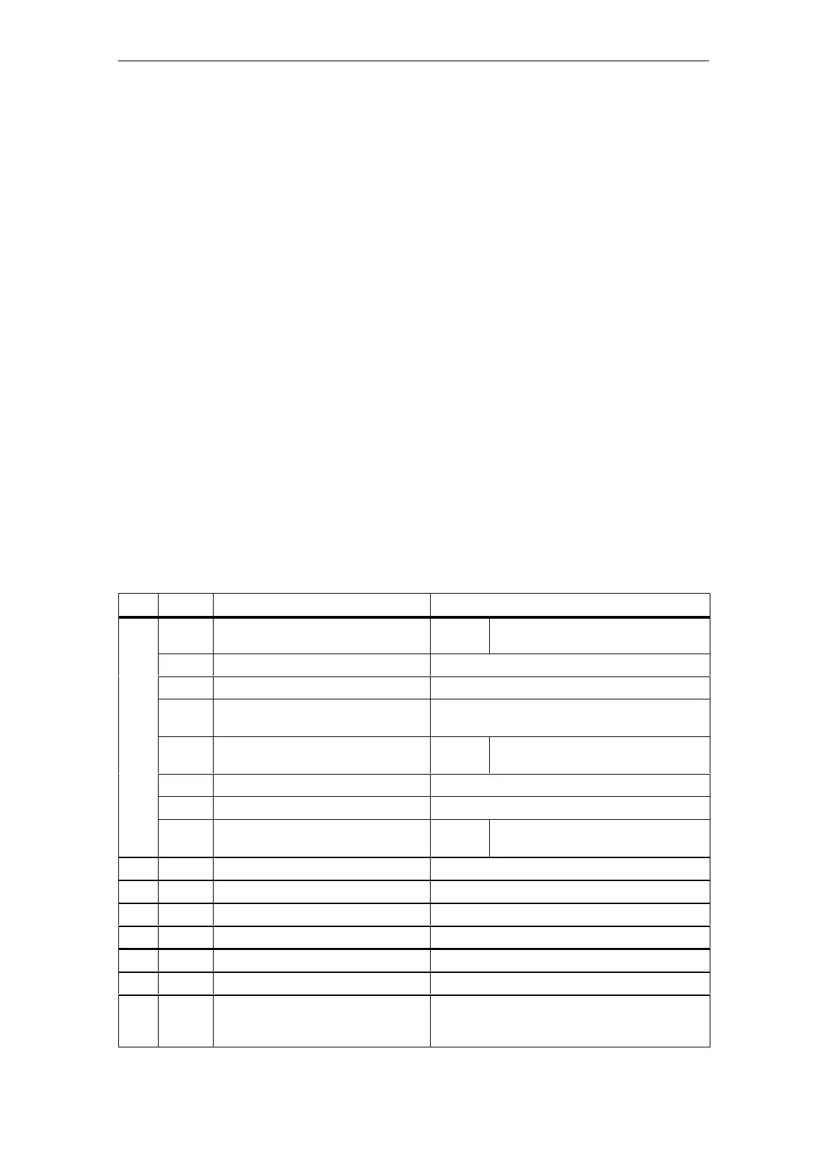
Table 5-22 Bytes x+4 to x+10 in the diagnosis of ET 200X
Byte
Bit Meaning Remarks
0 Error 1:
0:
Error
No error
1 Internal error Cause of fault is in BM
2 External error Cause of fault is in configuration of ET 200X
3 Module fault BM cannot access one or more plugged-in
modules
x+4
4 Load voltage 1:
0:
Error
No error
5 not assigned –
6 Parameters not assigned to module –
7 Parameter assignment 1:
0:
Error
No error
x+5 0 to 7 1B
H
Fixed
x+6 0 to 7 not assigned –
x+7 0 to 7 not assigned –
x+8 0 to 7 Module ID 55
H
for basic module
x+9 0 to 7 08
H
Length of channel-specific diagnosis
x+10 0 to 7 08
H
Fixed
x+11
to
x+19
0 to 7 not assigned –
 Loading...


