Technical Specifications
7-108
ET 200X Distributed I/O Device
EWA 4NEB 780601602-06
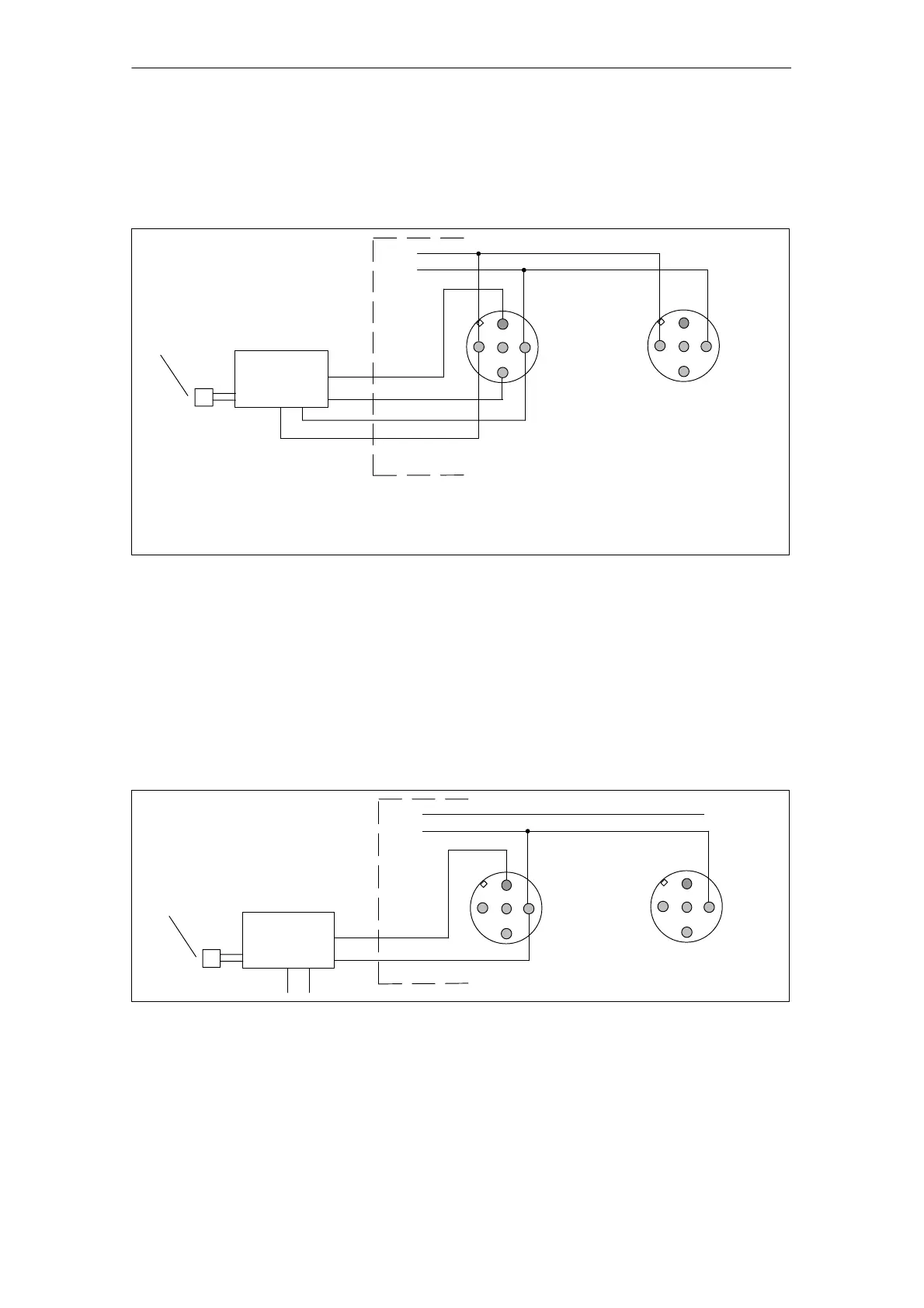
Four-wire measuring transducer at the EM 144 AI 2 I (20 mA)
The figure below shows how current sensors are connected as four-wire
measuring transducers to an EM 144 AI 2 I expansion module (20 mA).
* Made available by the ET 200X for the connected sensor;
1L+ of module must be used since a possible broken wire signal is possible
only with the sensor supply made available by the module.
M+
M–
Socket X1
Socket X2
Sensor,
e.g. pressure gauge
L+
1M
Connection of socket X2:
see socket X1
Four-wire
measuring
transducer
P
+
–
1M*
1L+*
1
2
3
4
1
2
3
4
Figure 7-26 Connection of current sensors (four-wire measuring transducers) to analog inputs (EM with
order number 6ES7 144-1GB31-0XB0)
Four-wire measuring transducer to EM 144 AI 2 I (4 to 20 mA)
The figure below shows how current sensors are connected as four-wire
measuring transducers to an EM 144 AI 2 I expansion module (4 to 20 mA ).
Note: There is no L+ available at pin 1 on the expansion module. You therefore
have to feed the supply voltage for the current sensor from an external source.
M+
M–
Socket X1
Socket X2
Sensor,
e.g. pressure gauge
L+ 1M
Connection of socket X2:
see socket X1
Four-wire
measuring
transducer
P
+
–
1M
1L+
1
2
3
4
1
2
3
4
Figure 7-27 Connection of current sensors (four-wire measuring transducers) to analog inputs (EM with
order number 6ES7 144-1GB41-0XB0)



 To Next Page