Technical Specifications
7-71
ET 200X Distributed I/O Device
EWA 4NEB 780601602-06
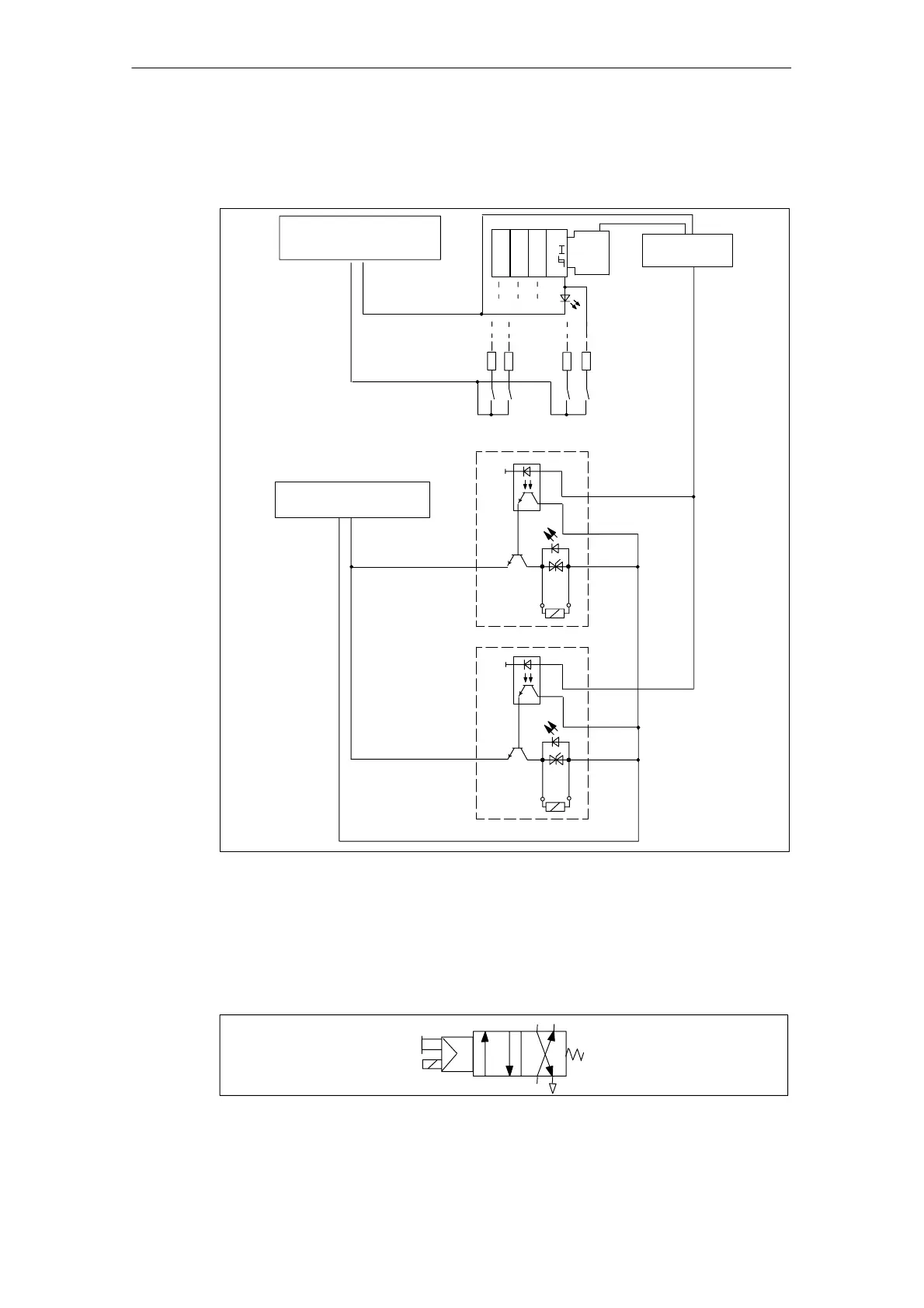
Basic circuit diagram
The basic circuit diagram of the expansion module is shown below.
Backplane bus
interface
Socket connections (see Table 7-34)
1L+
1M
Supply voltage for
electronic components and
sensors via backplane bus
So. X1
So. X2
2L+
2M
Load power supply via
backplane bus
1M
1M
Figure 7-17 Basic circuit diagram for EM 148-P DI 4 x DC 24V/DO 2 x P expansion module
Pneumatic connection diagram
The pneumatic connection diagram of a 4/2-way valve is shown below.
42
1 3/5
14
Figure 7-18 Pneumatic connection diagram of a 4/2-way valve