Installation
3-15
ET 200X Distributed I/O Device
EWA 4NEB 780601602-06
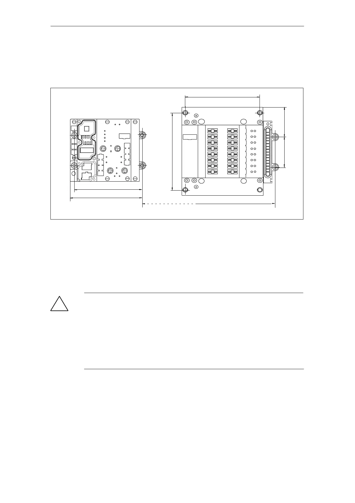
Dimensioned drawing for installation holes on the pneumatic interface module
The diagram below contains the dimensions and positions of the mounting screw
holes for one basic module and a pneumatic interface module.
120
n = number of expansion modules (without pneumatic interface module)
n + 120
126.8
53.5
48.25
132
109.5
Figure 3-10 Dimensions of installation holes on the pneumatic interface module
Disassembling modules featuring pneumatic functionality
Please take the following important note into account before disassembling
pneumatic and pneumatic interface modules:
!
Caution
Before disassembling expansion modules featuring pneumatics, you must:
disconnect all supply voltages for the ET 200X
disconnect the supply of compressed air
If you fail to comply with these rules, the following effects are possible:
damage to module electronics
uncontrollable motions of detached tubing
unwanted motions of the actuators connected