Technical Specifications
7-18
ET 200X Distributed I/O Device
EWA 4NEB 780601602-06
7.4 BM 142 DO 4 x DC 24V/2A basic module
(6ES7 142-1BD22-0XB0)
Features
The BM 142 DO 4 x DC 24V/2A basic module, order number
6ES7 142-1BD22-0XB0, has the following features:
4 digital outputs
Output current 2 A per output
Rated load voltage 24 VDC
Suitable for solenoids, DC contactors and indicator lights
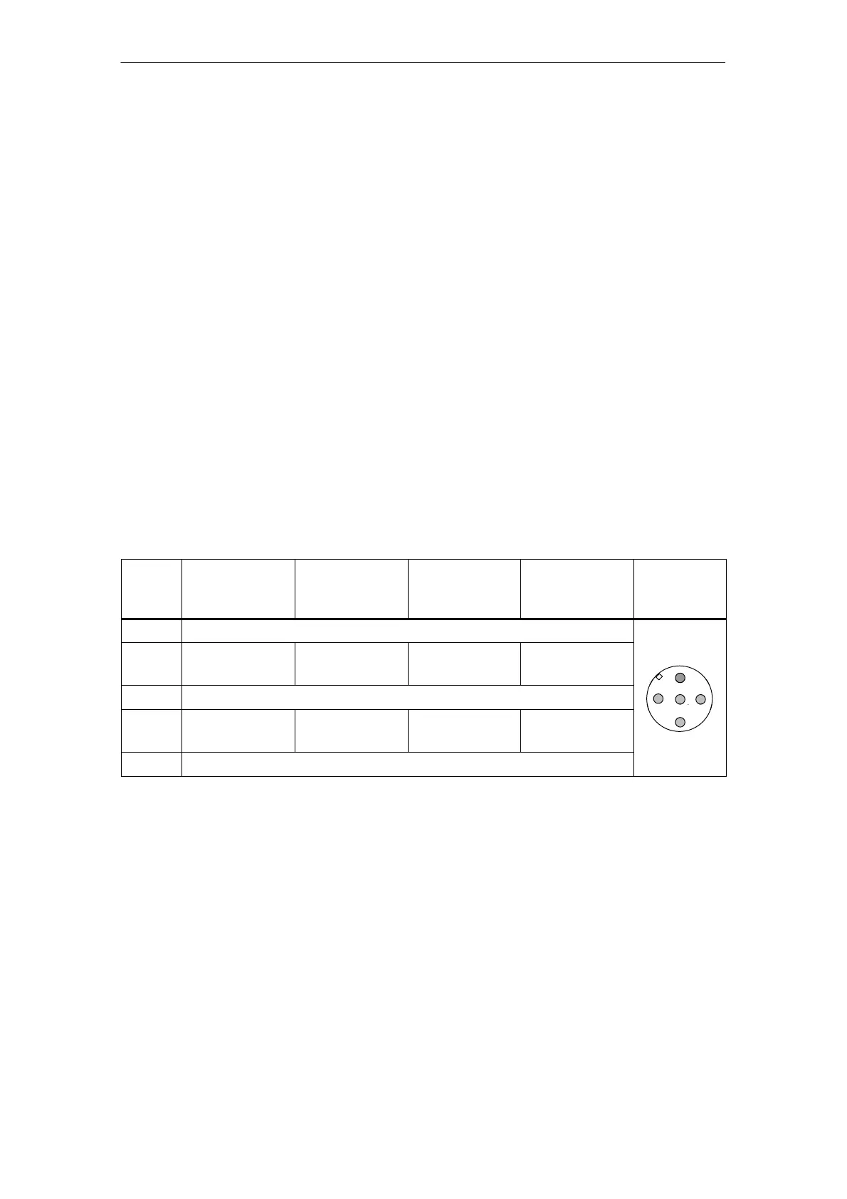
Pinout of the sockets for DO
The following table shows the pinout of the four sockets used to connect the digital
outputs. The connector wiring is described in Section 4.4.4. You can find the layout
of the sockets X1 to X4 on the module in Appendix C.
Table 7-8 Pinout of the sockets for 4-channel digital outputs
Pin Assignment of
socket X1
Assignment of
socket X2
Assignment of
socket X3
Assignment of
socket X4
Front view
of socket
(Front)
1 –
2 Output signal,
channel 1*
– Output signal,
channel 3*
–
2
3 Chassis ground, load power supply
1
2
3
5
4 Output signal,
channel 0
Output signal,
channel 1*
Output signal,
channel 2
Output signal,
channel 3*
4
5 PE
* Note: Channel 1 and channel 3 are only allowed to be used at one socket (X1/X2 or X3/X4).
Covering up unused connections
You must seal off any connections which are not required with M12 screw caps, in
order to ensure that the degree of protection (IP 65, IP 66 or IP 67) is achieved.
 Loading...


