Positioning Axes (P2)
17.2 Permanently assigned PLC axis
Turning, Milling, Nibbling
310 Function Manual, 11/2012, 6FC5397-1CP10-5BA0
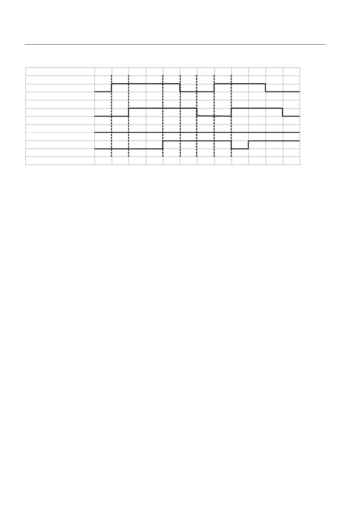
WR3/&D[LV
IURP3/&D[LV
3RVLWLRQLQJD[HVDFWLYH
3RVLWLRQUHDFKHG
6WDUW
(UURUV
Figure 17-2 Pulse diagram error condition
8. First function activation via positive edge of
Start
9.
Positioning axis active
= 1 shows that the function is active and that the output signals are
valid
10. Negative acknowledgement
Error
= 1 and
Positioning axis active
= 1
11. Reset function activation after receipt of acknowledgment
12. Signal change via function
13. Second function activation via positive edge of
Start
14.
Positioning axis active
= 1 shows that the function is active and that the output signals are
valid
Cancel
The PLC axis control cannot be aborted by means of parameter "Start", but only by means of
the axial interface signals (e.g. delete distancetogo). The axial interface also returns status
signals of the axis that may need to be evaluated (e.g. exact stop, traverse command).
Axis disable
With the axis disabled, an axis controlled via PLC axis control will not move. Only a
simulated actual value is generated. (Behavior as with NC programming).
Fault detection
If a PLC axis control could not be executed, this is indicated by the error signal
(V390x 3000.1 or V390x 3000.0) with 'logical 1'. The cause of the error is coded as an error
number.

 Loading...


