6 Pro
rammin
the control
6
03/2006
6.9 Axes and spindles
6-123
© Siemens AG 2006 All Rights Reserved
SINUMERIK 840D/810D Start-Up Guide (IADC) – 03/2006 Edition
6.9.18 Spindle synchronization
The spindle must synchronize its position with the measuring system. It is al-
ways synchronized with the zero marker of the encoder or with a sensor signal
that is connected to the drive module of the SIMODRIVE 611D. MD 34200
ENC_REFP_MODE is used to specify which signal is used for the synchroniza-
tion (zero marker (0) or sensor (1))
S After activation of the control if the spindle is moved with a programming
command.
S The “Resynchronize spindle 1/2” signal removes the “Referenced/Synchro-
nized 1/2” signal that resynchronizes the spindles with the next reference
signal.
S After every gear step change (MD 31040: ENC_IS_DIRECT=0)
S The spindle goes out of synchronism if a speed above the encoder limit fre-
quency is programmed. When the speed drops to below the encoder limit
frequency, the spindle is re-synchronized. If the synchronized state has
been lost, it is impossible to implement functions such as rotational feedrate,
constant cutting velocity, tapping with and without compensating chuck, po-
sitioning and axis modes.
MD 34100: REFP_SET_POS (reference point value, zero marker position). This
MD is used to enter the position of the reference signal for synchronization.
MD 34090: REFP_MOVE_DIST_CORR (reference point move, zero marker
move)
The zero mark offset resulting from the synchronization process is entered here.
MD 34200: ENC_REFP_MODE (position measuring system type)
NST “Resynchronize spindle 1, 2” (DB31, ... DBX16.4 or 16.5)
NST “Referenced/synchronized” 1, 2” (DB31, ... DBX60.4 or 60.5)
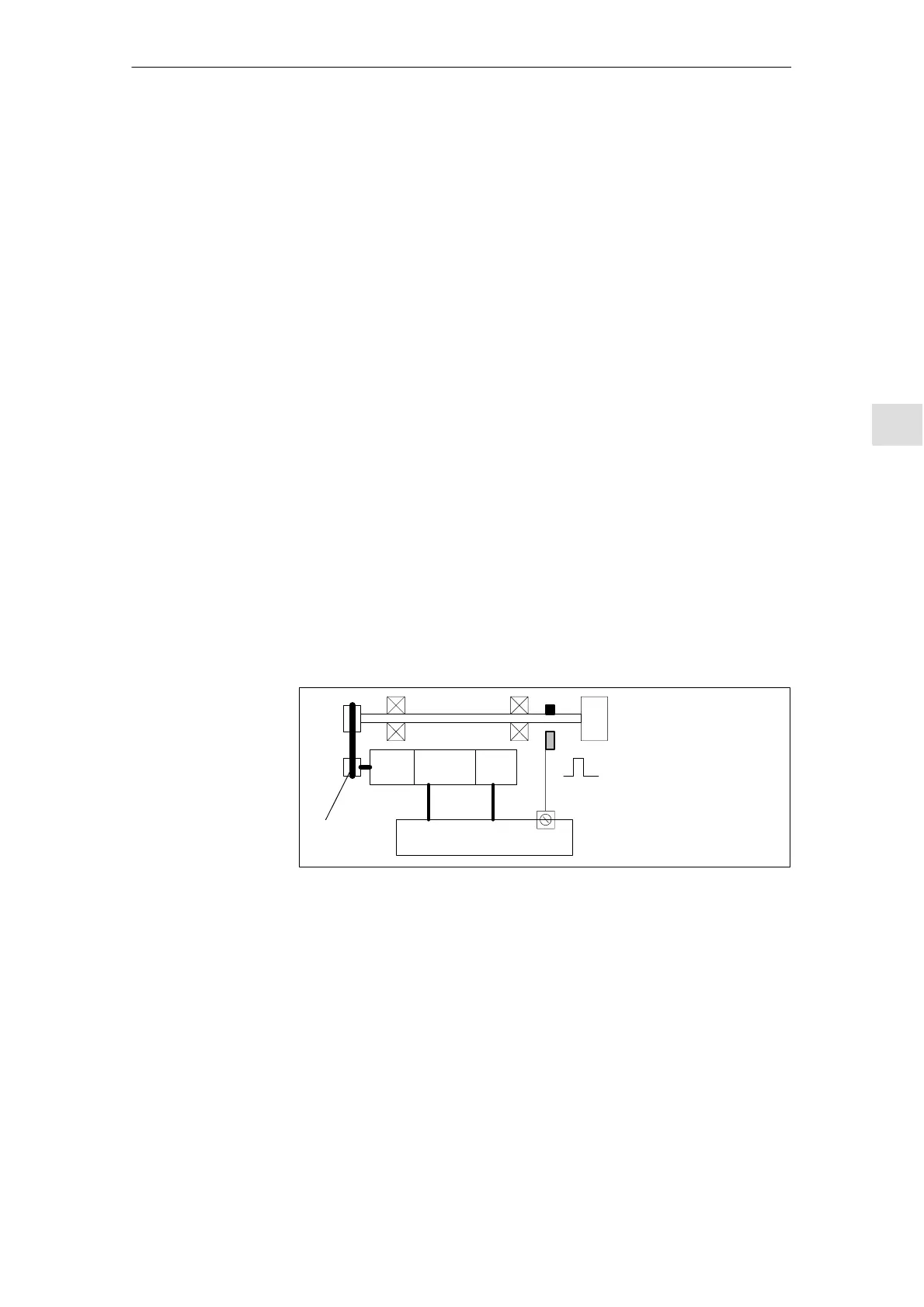
Motor Motor
encoder
MSD module SIMODRIVE 611D
Chuck
BERO
Power
connection
Motor enco-
der cable
Gearing
Toothed belt
Fig. 6-22 Synchronization via an external reference signal (BERO)
When is
synchronization
necessary?
Machine data and
interface signals

 Loading...


