5
03/2006
5.2 NCU controls and displays
5-38
© Siemens AG 2006 All Rights Reserved
SINUMERIK 840D/810D Start-Up Guide (IADC) – 03/2006 Edition
5.2 NCU controls and displays
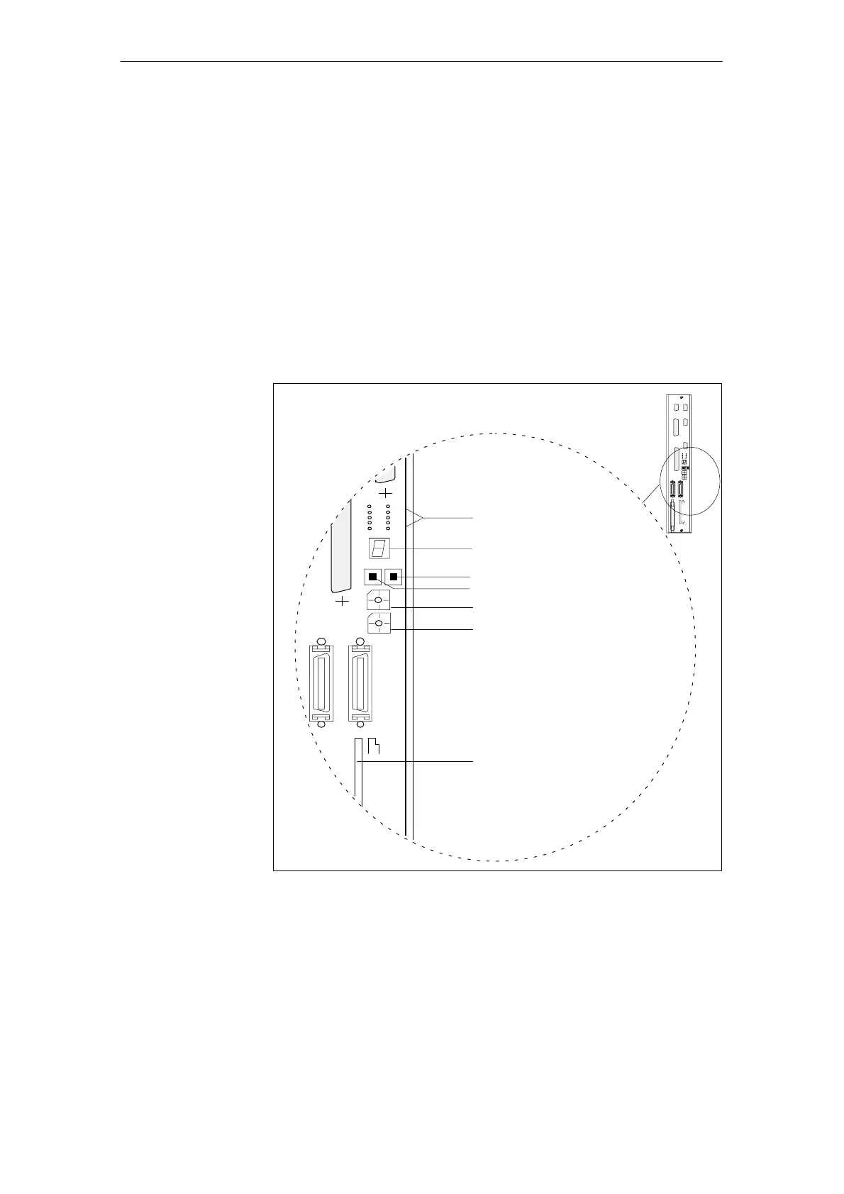
Fig. 5-1 below shows the controls and displays on the NCU that are important
for powering on and powering up the SINUMERIK 840D:
S Various error and status LEDs
S 7-segment status display (H3)
S NMI button (S2)
S RESET button (S1)
S NC start-up switch (S3)
S PLC start-up switch (S4)
S PCMCIA slot
Various error and status LEDs
Status display (H3)
RESET button (S1)
NMI button (S2)
PLC start-up switch (S4)
NC start-up switch (S3)
PCMCIA slot (X145)
MEMORY CARD
X172
S3
X130B
X130A
S4
Reset NMI
+5
V
NF
CF
CB
CP
PR
P
S
P
F
PF0
–
Fig. 5-1 SINUMERIK 840D controls and displays on the NCU
A detailed description of the controls and displays can be found in the following
documentation:
Reference material: /PHD/ Device Manual, NCU Configuration
Important controls
and displays for
power up
5 Power-On and Power-U

 Loading...


