10
03/2006
10.2 Measuring functions
10-179
© Siemens AG 2006 All Rights Reserved
SINUMERIK 840D/810D Start-Up Guide (IADC) – 03/2006 Edition
10.2 Measuring functions
There are a range of measuring functions for displaying the time and frequency
behavior of drives and controls in graph form on screen. Test signals of variable
duration are applied to the drives for this purpose.
The test setpoints are adapted to the application by means of measuring and
signal parameters. The units of these parameters depend on the measuring
function or operating mode. The following conditions apply for the units of these
measuring and signal parameters:
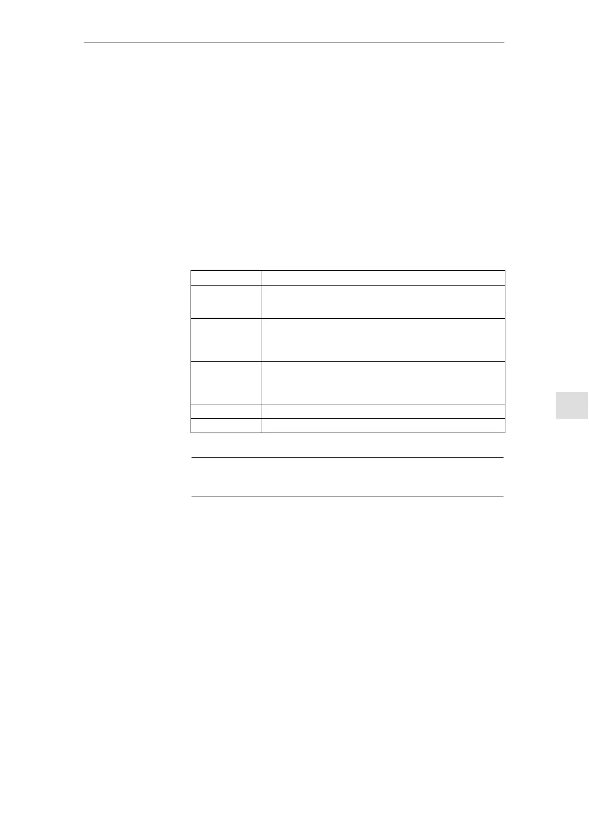
Table 10-1 Quantities and units for measuring and signal parameters
Quantity Unit
Torque Specified in percent referred to the peak torque of the power section
used. The torque is calculated for the power section from:
MD 1108 x MD 1113
Velocity/speed Metric system:
Specified in mm/min or rev/min for linear or rotary motions
Inch system:
Specified in inch/min or rev/min for linear or rotary motions
Distance Metric system:
Specified in mm or degrees for linear or rotary motions
Inch system:
Specified in inches or degrees for linear or rotary motions
Time Specified in ms
Frequency Specified in Hz
Note
All the parameters are preceded with 0.
The measuring functions must be started in “JOG” mode to ensure that there
are no accidental traversing motions due to part programs.
Explanation
Measuring/signal
parameters
Requirements for
starting measuring
functions
10 Drive O
timization

 Loading...


