6 Pro
rammin
the control
6
03/2006
6.6 System data
6-67
© Siemens AG 2006 All Rights Reserved
SINUMERIK 840D/810D Start-Up Guide (IADC) – 03/2006 Edition
6.6 System data
6.6.1 Basic settings
The control works on the basis of clock cycles that are defined via machine
data. The system basic cycle is specified in seconds; the other cycle times are
obtained as multiples of the system basic cycle.
The clock cycles are optimized by default and should only be changed if the
requirements of the NCK cannot be met with the default values.
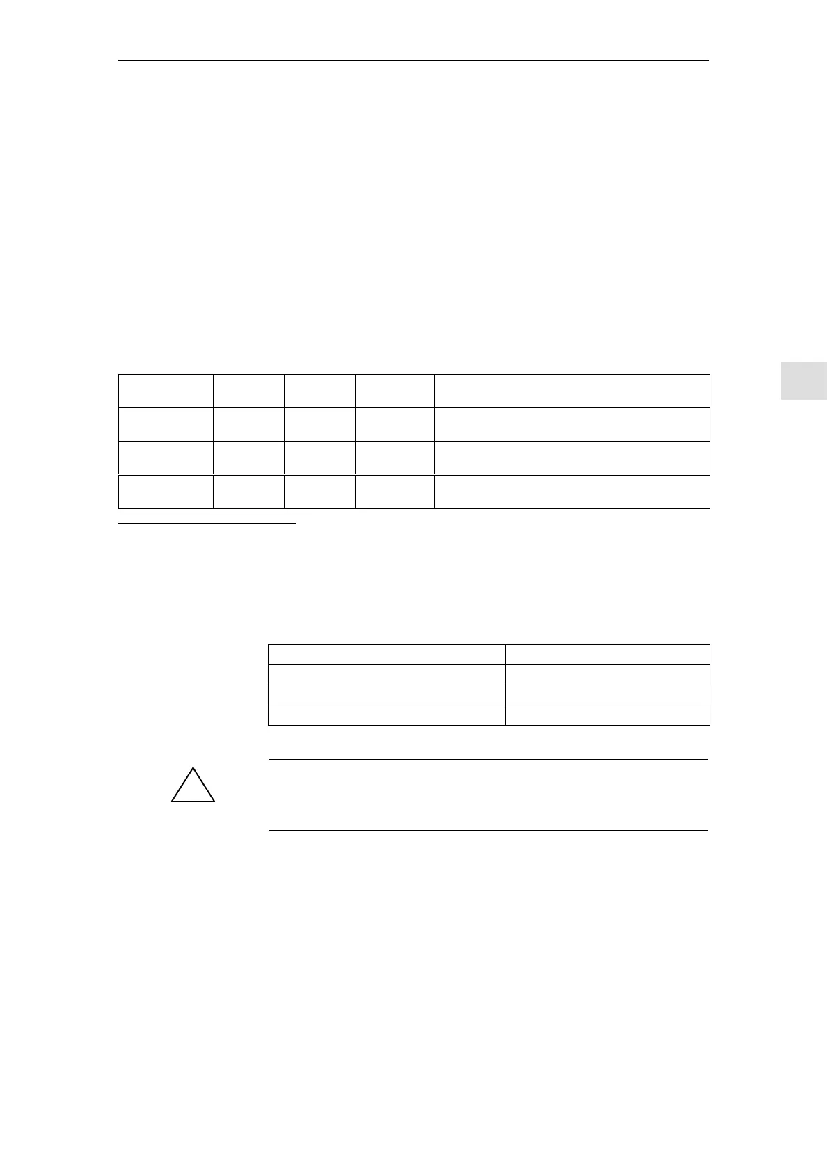
The following cycle times are used by default:
Table 6-10 Clock cycles – default values for the control
Cycle 840D
NCU 571
840D
NCU 572
840D
NCU 573
Setting via MD
System basic
cycle in s
6 ms 4 ms 4* / 8
#
ms MD 10050: SYSCLOCK_CYCLE_TIME
Position control
cycle as a factor
6 ms 4 ms 4* / 8
#
ms MD 10060: POSCTRL_SYSCLOCK_TIME_RATIO
Interpolator cy-
cle as a factor
18 ms 12 ms 12
*
/ 40
#
ms MD 10070: IPO_SYSCLOCK_TIME_RATIO
* with 2 channel and 12 axes
#
with > 2 channels
The machine data for cycle times is set as follows:
If MD ... = ... Then the ... = ...
SYSCLOCK_CYCLE_TIME = 0.002 System basic cycle = 2 ms
POSCTRL_SYSCLOCK_TIME_RATIO = 1 Position control cycle = 2 ms (1 2 ms)
IPO_SYSCLOCK_TIME_RATIO = 3 Interpolator cycle = 6 ms (3 2 ms)
!
Warning
If you have changed the clock cycles, check that the operating response of the
control is correct in all operating modes before ending the start-up process.
A control is switched from the metric system to an inch system with
MD 10240: SCALING_SYSTEM_IS_METRIC (basic system is metric).
The additional conversion factor is specified in
MD 10250: SCALING_VALUE_INCH (conversion factor for switching to the
INCH system, factor = 25.4).
After power ON the existing data is converted to inches and displayed. After
switchover data must be entered in inches.
Control clock
cycles
General example
for cycle settings
Switching from
metric to Inch

 Loading...


