10
03/2006
10.4 Frequency response measurement
10-188
© Siemens AG 2006 All Rights Reserved
SINUMERIK 840D/810D Start-Up Guide (IADC) – 03/2006 Edition
10.4.3 Scanning position control loop
The behavior when transferring to the active position measuring system is
always analyzed. The NCK generates an error message if the function is activa-
ted for a spindle without position measuring system. Various lists of measuring
parameters are offered depending on which basic setting is selected.
1. Setting the traveling range monitoring and the enabling logic on the
main screen.
One of three different types of measurement can be selected:
S Reference frequency response
S Setpoint step change
S Setpoint ramp
2. Setting the necessary parameters on the measuring parameters screen
3. Displaying the measurement result on screen using the Display soft key
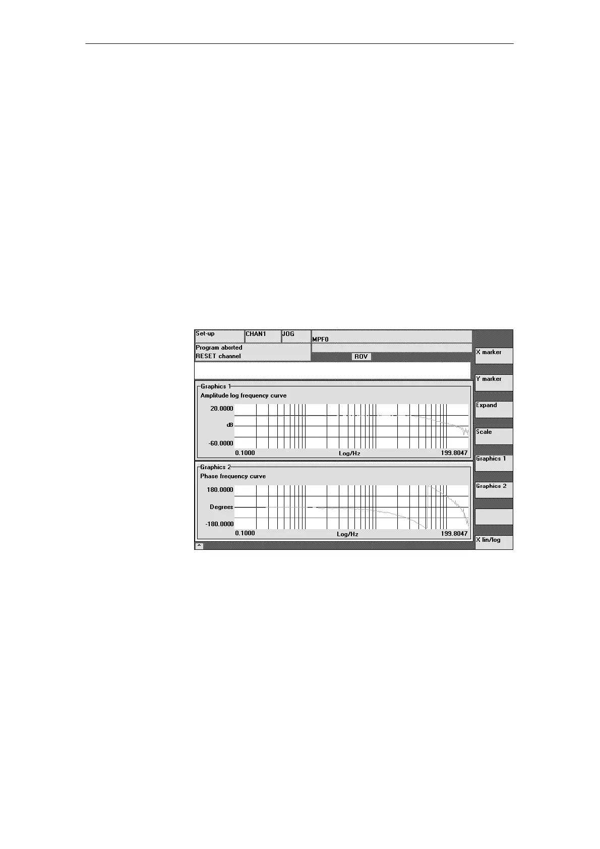
Fig. 10-4 Display diagram: Example of a position control loop
The reference frequency response measurement determines the transmission
response of the position controller in the frequency range (active position mea-
suring system). The parameters for the setpoint filters, K
v
value and bias control
should be set to ensure there is as little resonance as possible throughout the
frequency range. In the case of dips in the frequency response, the setting of
the feedforward control balancing filters should be checked. Excessive reso-
nance requires
1. Decrease in K
V
value
2. Canceling the bias control value
3. Use of setpoint filters
The effects of these measures can also be checked in the time range.
Functionality
Procedure
Reference
frequency
response
10 Drive O
timization

 Loading...


