3
03/2006
3.4 MPI default configuration for SINUMERIK 810D
3-28
© Siemens AG 2006 All Rights Reserved
SINUMERIK 840D/810D Start-Up Guide (IADC) – 03/2006 Edition
Example:
GD circuits 1 and 2 are assigned by “Communication Configuration” as a result
of the PLC–PLC cross-communication. A first MSTT on the MPI can then be
assigned to GD circuit 3 (bus address 9 or 10), and a second MSTT on the MPI
to GD circuit 4 (bus address 7 or 8).
3.4 MPI default configuration for SINUMERIK 810D
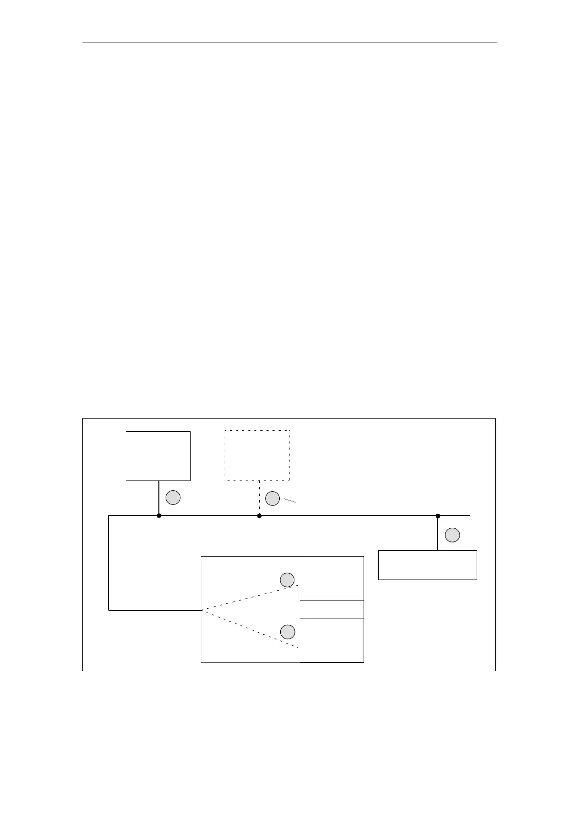
SINUMERIK 810D with PCU and one machine control panel (MSTT) or inter-
face for customer’s operating panel
At least firmware release V 03_01_01 for
S MCP
S interface for customer’s operating panel
from version 2.x
All MPI bus nodes operate at 187.5 kbaud.
Every node on the MPI bus must have a bus address (0...15).
PCU
PLC
NCK
MSTT/interface for
customer’s operating panel
MPI bus
187.5 kbaud
2
1
0
14
3
Bus addresses
X122
SINUMERIK 810D
PG/start-up tool
Fig. 3-7 Standard application for SINUMERIK 810D
Standard
application
Hardware
requirements
STEP7
MPI baud rate
Bus addresses
3 Settin
s, MPI/BTSS

 Loading...


