9
9-171
© Siemens AG 2006 All Rights Reserved
SINUMERIK 840D/810D Start-Up Guide (IADC) – 03/2006 Edition
Axis/Spindle Dry Run
9.1 Requirements
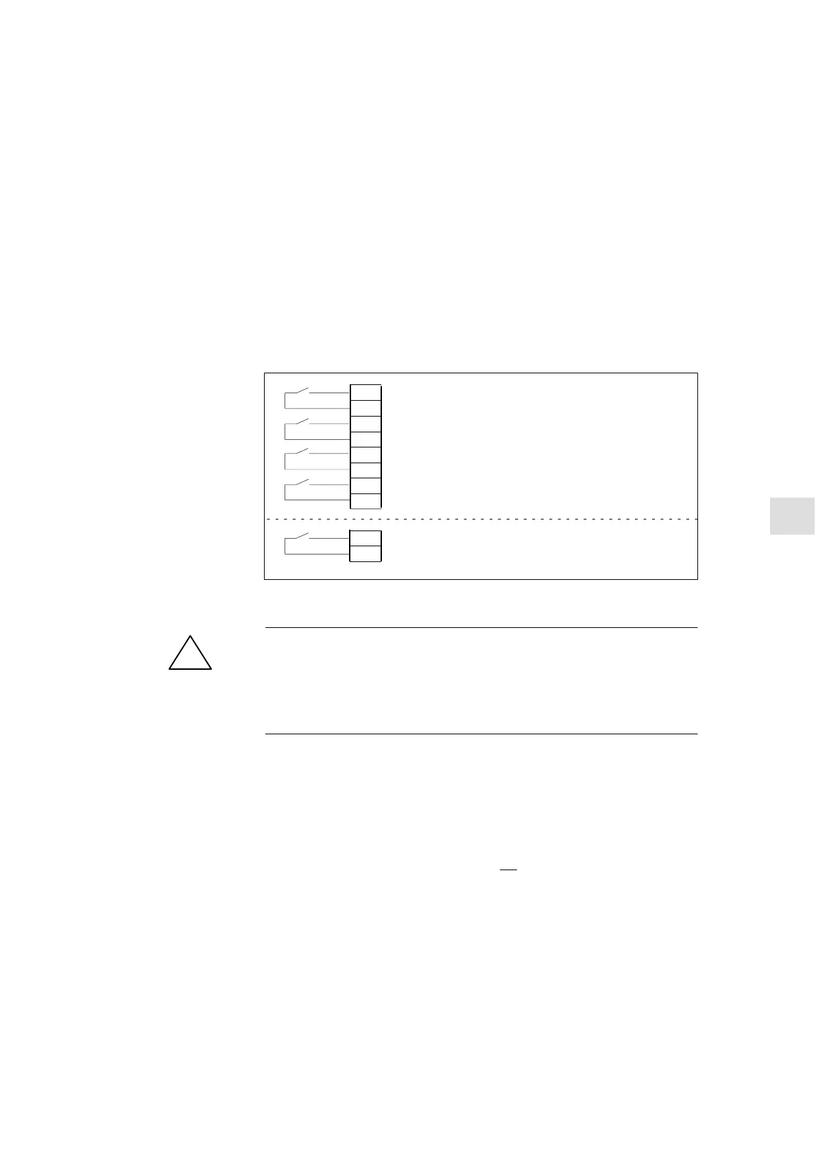
To allow an axis to be moved by the control, enabling terminals on the drive
must be powered and enable bits set at the interface.
Pulse enable
+24 V
+24 V
63
9
64
9
48
9
Drive enabling command
DC-link start
+24 V
Pulse enable
+24 V
663
9
MS (Mains supply) module
Drive module
Set-up mode
+24 V
112
9
Reference material: /PJU/ Converter Configuration Guide
!
Warning
Despite the “Axis disable” command via terminal 663, dangerous voltages may
still be present at the drive control output terminals.
The “Axis disable” command via terminal 663 is not suitable for electrical isola-
tion or for use as a drive deactivation mechanism.
The following signals must be made available at the PLC interface for axis or
spindle:
NST “Controller enable” (DB31–61, DBX2.1)
NST “Pulse enable” (DB31–61, DBX21.7)
NST “Position measuring system 1 or 2” (DB31–61, DBX1.5, DBX 1.6)
The following signals on the interface must not
be set or else the axis/spindle
motion will be disabled:
NST “Feed/spindle correction switch” (DB31–61, DBB0) not set to 0%
NST “Axis/spindle disable” (DB31–61, DBX1.3)
NST “Adjustment mode” (DB31–61, DBX1.4)
NST “Remaining distance/spindle reset” (DB31–61, DBX2.2)
NST “Feed stop/ spindle stop” (DB31–61, DBX4.3)
NST “Travel button disable” (DB31–61, DBX4.4)
NST “Power-up sensor disable” (DB31–61, DBX20.1)
Enables for axes
Enables on the drive
Enabling via
PLC interface
9

 Loading...


