10
03/2006
10.4 Frequency response measurement
10-183
© Siemens AG 2006 All Rights Reserved
SINUMERIK 840D/810D Start-Up Guide (IADC) – 03/2006 Edition
10.4 Frequency response measurement
10.4.1 Scanning the torque control loop
It is only necessary to scan the torque control loop for diagnostic purposes in
the event of an error or if standard data was not used for the particular motor/
power section combination, leading to unsatisfactory speed controller frequency
responses.
Note
The user must take special safety precautions before measuring the torque
control loop for vertical axes that have no external weight compensation (drive
must be securely clamped).
1. Setting the traveling range monitoring and the enabling logic on the main
screen.
2. Setting the necessary parameters on the measuring parameters screen
3. Displaying the measurement result on screen using the Display soft key
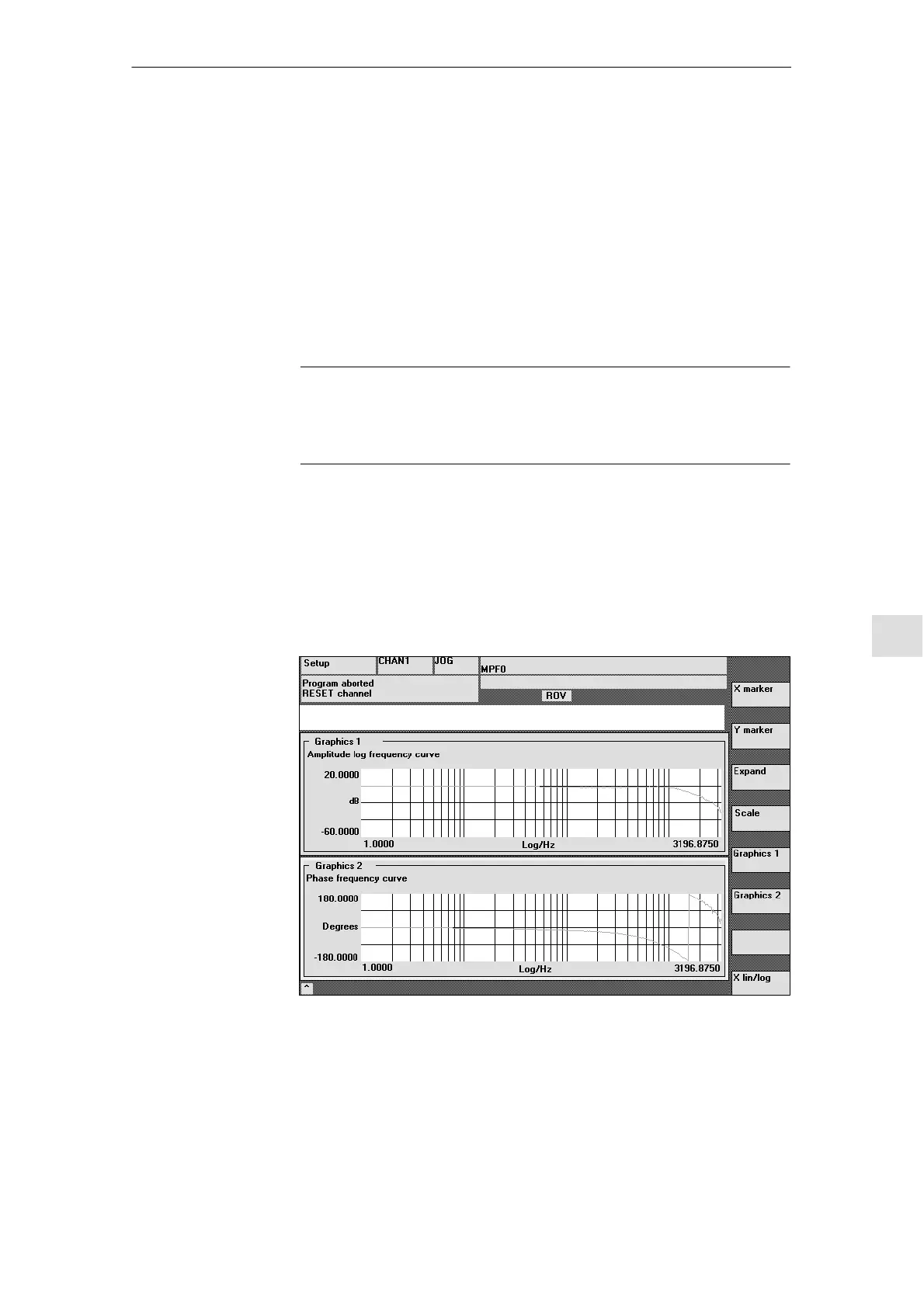
Fig. 10-1 Display diagram: Example of a current control loop
Amplitude
This parameter determines the test signal amplitude (unit: specify the peak
torque as %). Values between 1 and 5% are suitable.
Functionality
Procedure
Measuring
parameters
10 Drive O
timization

 Loading...


