6 Pro
rammin
the control
6
03/2006
6.7 Memory configuration
6-71
© Siemens AG 2006 All Rights Reserved
SINUMERIK 840D/810D Start-Up Guide (IADC) – 03/2006 Edition
6.7 Memory configuration
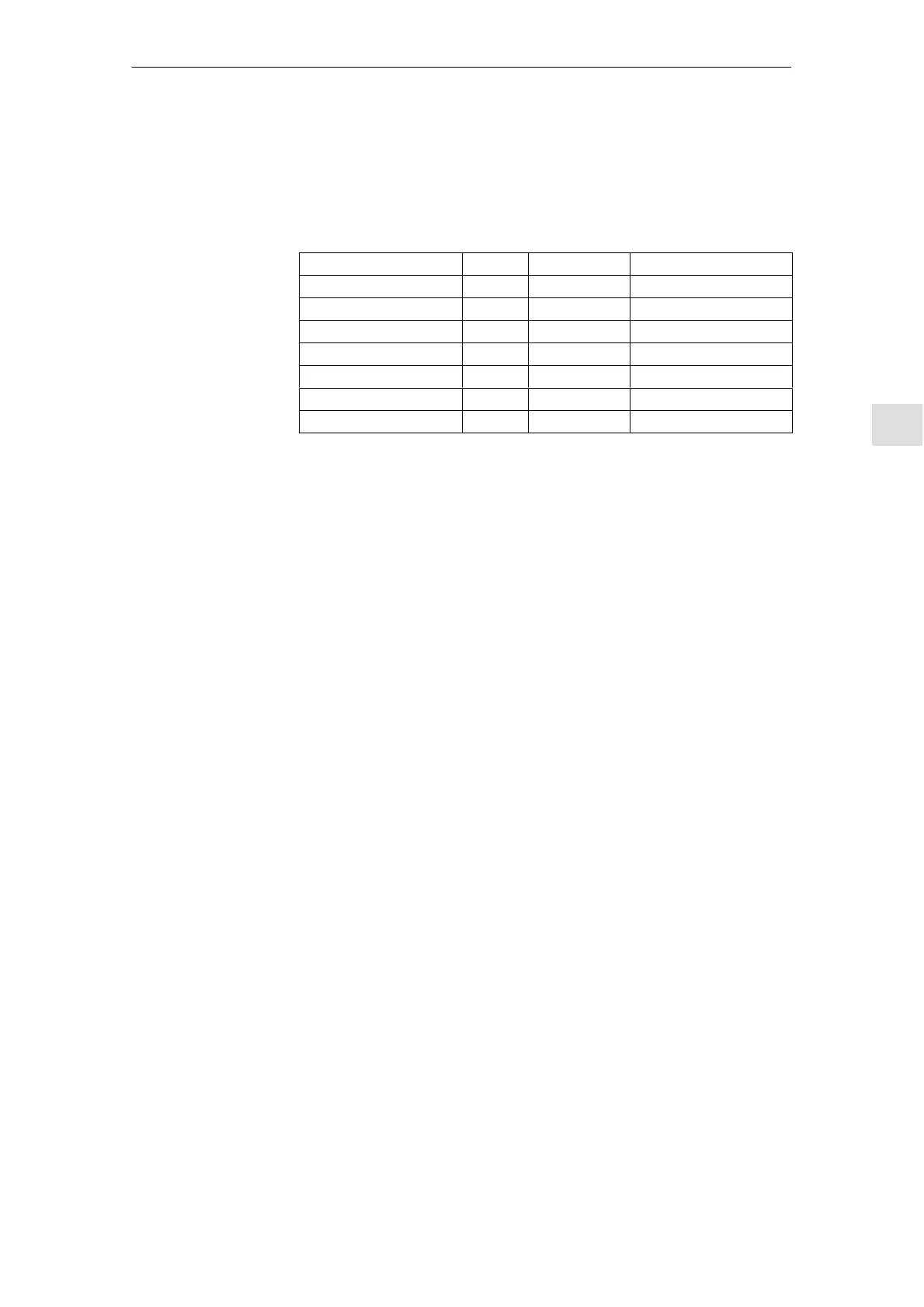
The following table shows the hardware structure of the available NCK CPU:
D-RAM S-RAM PCMCIA
NCU 561.4 32 MB 4 MB 8 MB
NCU 571.3 2 x 4 MB 4 MB 8 MB
NCU 571.4 32 MB 4 MB 8 MB
NCU 572.3 32 MB 2 MB 8 MB
NCU 572.4 32 MB 4 MB* 8 MB
NCU 573.4 64 MB 4 MB 8 MB
NCU 573.5 64 MB* 3 MB* 8 MB
*) Can be ordered as options, see Catalog NC 60
The memory areas for user data in the NCK are set to the appropriate defaults
after an NCK general reset. The following areas can be adjusted to achieve
optimum utilization of the available RAM:
S Part programs
S Tool management
S Tool offsets
S Global user data
S Curve tables
S Compensations (e.g. LEC)
S File system/program memory
S Protection areas
The memory breakdown must take place before the NC is actually started up
since, if it is divided up again, all the buffered user data will be lost (e.g. part
programs, drive data).
Machine data, setting data and options are not erased.
Hardware structure
Memory areas

 Loading...


