6 Pro
rammin
the control
6
03/2006
6.9 Axes and spindles
6-89
© Siemens AG 2006 All Rights Reserved
SINUMERIK 840D/810D Start-Up Guide (IADC) – 03/2006 Edition
6.9.5 Parameter settings for incremental measuring systems
The following table lists all the parameters which have to be entered for encoder
adjustment.
Table 6-16 Machine data for matching rotary encoders
Machine data Linear axis Rotary axis
Encoder on
motor
Encoder on
machine
Encoder on
motor
Encoder on
machine
30300: IS_ROT_AX 0 0 1 1
31000: ENC_IS_LINEAR 0 0 0 0
31040: ENC_IS_DIRECT 0 1 0 1
31020: ENC_RESOL Marks/rev Marks/rev Marks/rev Marks/rev
31030: LEADSCREW_PITCH mm/rev mm/rev – –
31080: DRIVE_ENC_RATIO_NUMERA Motor rev. Load rev. Motor rev. Load rev.
31070: DRIVE_ENC_RATIO_DENOM Encoder rev. Encoder rev. Encoder rev. Encoder rev.
31060: DRIVE_AX_RATIO_NUMERA Motor rev. Motor rev. Motor rev. Motor rev.
31050: DRIVE_AX_RATIO_DENOM Spindle rev. Spindle rev. Load rev. Load rev.
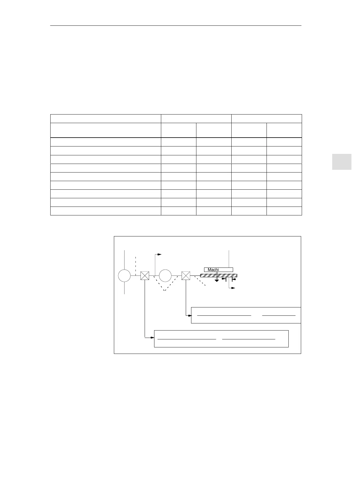
M
IS_ROT_AX=0
Machine table
ENC_IS_LINEAR=0
ENC_RESOL
G
DRIVE_AX_RATIO_NUMERA No. of motor rev.
DRIVE_AX_RATIO_DENOM
=
No. of spindle rev.
ENC_IS_DIRECT=0
LEADSCREW_PITCH
n
Encoder
Resolver
gearbox
n
Motor
Load
gearbox
n
Spindle
Leadscrew
DRIVE_ENC_RATIO_NUMERA
DRIVE_ENC_RATIO_DENOM
+
Numberofmotorrevolutions
Numberofencoderrevolutions
Fig. 6-8 Linear axis with motor-mounted rotary encoder
Rotary encoders
Linear axis with
rotary encoder at
the motor

 Loading...


