6 Pro
rammin
the control
6
03/2006
6.10 Linear motors (1FN1 and 1FN3 motors)
6-137
© Siemens AG 2006 All Rights Reserved
SINUMERIK 840D/810D Start-Up Guide (IADC) – 03/2006 Edition
7. Determine the commutation angle offset
The commutation angle offset is determined as follows:
a) Select identification method via MD 1075. Possibly adapt other
machine data for rotor position identification.
b) Save the boot files and perform NCK reset.
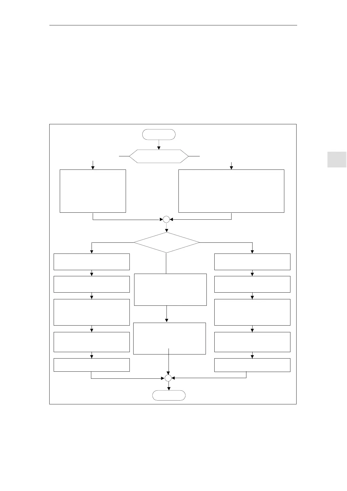
c) Depending on which measuring system is used, continue as follows:
With an incremental measuring system:
Zero markers?
End
START
The coarse synchroniza-
tion is obtained from the
Hall sensor signals (C/D
track) on switching on
Several zero markers with cams
or distance-coded reference
markers from VSA 06.07.07
No zero marker, several zero mar-
kers without cam distance-coded
reference markers from up to VSA
06.07.07
There is no selection of the zero
marker and the commutation angle
offset is not accepted
Reference axis on the NCK side
Yes, Hall sensor
boxes present
No, Hall sensor boxes
not present
If the enables are set, a rotor position identification
is carried out immediately.If the rotor position identi-
fication is unsuccessful, the appropriate error mes-
sage is output. Once the causes of the fault have
been eliminated and the error message acknowled-
ged, another attempt at identification is made.
Are Hall sensor
boxes present?
Set MD 1017 (”Start-up help”) to 1
Set MD 1017 (”Start-up help”) to 1
Move axis over the zero marker,
“JOG” operating mode
When it moves over the zero mar-
ker, the commutation angle offset
is entered in MD 1016
One zero marker
When it moves over the zero mar-
ker, the commutation angle offset
is entered in MD 1016
Alarm 300799 appears (”Save boot
files and perform NCK reset”)
Alarm 300799 appears (”Save boot
files and perform NCK reset”)
Save boot files and perform
NCK reset
Save boot files and perform
NCK reset
Fig. 6-31 Incremental measuring system
Incremental
measuring system

 Loading...


