6 Pro
rammin
the control
6
03/2006
6.10 Linear motors (1FN1 and 1FN3 motors)
6-153
© Siemens AG 2006 All Rights Reserved
SINUMERIK 840D/810D Start-Up Guide (IADC) – 03/2006 Edition
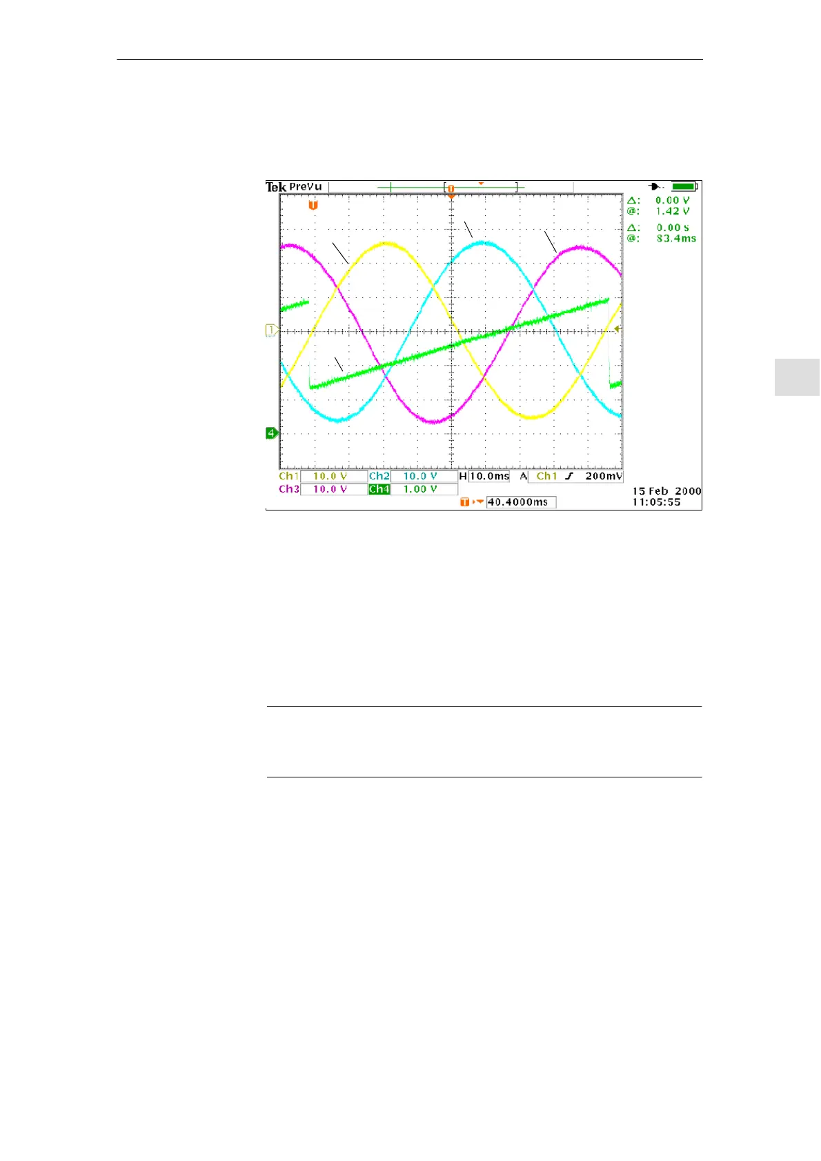
After connecting the oscilloscope, first move the drive over the zero marker that
the drive is synchronized.
Ch1/Phase U
Ch3/Phase W
Ch2/Phase V
Ch4
Fig. 6-45 Determining the commutation angle offset by measuring the EMF and
normalized electrical rotor position via DAC in a positive drive direction
Definition of channels (Ch1 ... Ch4):
S Ch1: EMF Phase U to star point
S Ch2: EMF Phase V to star point
S Ch3: EMF Phase W to star point
S Ch4: Scaled electrical rotor position via DAU measured signal
Note
If you select the “Scaled, electrical rotor position” measured signal, the SHIFT
factor should be changed from 7 to 8 and the offset value from –1.25V to –2.5V.
For a synchronized drive, the difference between the EMF/phase U and the
electrical rotor position should not exceed $10_.
If the difference is greater, the position of the zero marker must be moved in the
software in MD 1016 “COMMUTATION_ANGLE_OFFSET”.
Determining the
commutation
angle

 Loading...


