10
03/2006
10.4 Frequency response measurement
10-185
© Siemens AG 2006 All Rights Reserved
SINUMERIK 840D/810D Start-Up Guide (IADC) – 03/2006 Edition
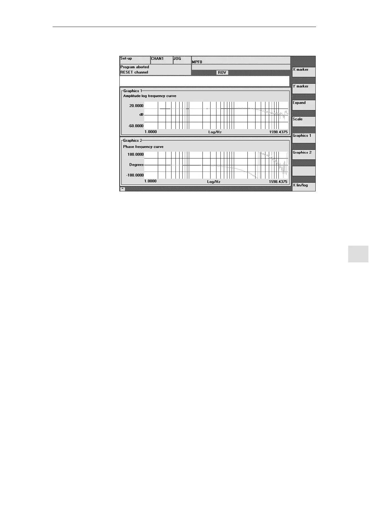
Fig. 10-2 Display diagram: Example of speed control loop
The guide frequency response measurement determines the transmission
response of the speed controller. The response range should be as wide as
possible and without resonance. It may also be necessary to use stop or low-
pass filters (611D). Particular care must be taken to prevent resonance within
the speed controller limit frequency range (stability limit approx. 200-500 Hz).
Alternatively, the interference frequency response can be recorded to evaluate
the noise suppression of the controller.
Amplitude
This parameter determines the test signal amplitude. This should give rise to
only a very low speed of a few (approximately 1 to 2) revs/min at the motor end.
Offset
The measurement requires a low speed offset of just a few motor revolutions
per minute. The set offset must be greater than the amplitude.
From SW 4.1:
S The offset is started up via an acceleration ramp.
S The acceleration value is defined for an
Axis: MD 32300: MAX_AX_ACCEL
Spindle: MD 35200: GEAR_STEP_SPEEDCTRL_ACCEL
MD 35210: GEAR_STEP_POSCTRL_ACCEL
S Where: Acceleration value = 0, no ramp
Acceleration value > 0, ramp active
S The actual measuring function is not activated until the offset value is
reached.
Guide frequency
response
Interference
frequency
response
Measuring
parameters for
guide and
interference
frequency
response
10 Drive O
timization

 Loading...


