10
03/2006
10.4 Frequency response measurement
10-190
© Siemens AG 2006 All Rights Reserved
SINUMERIK 840D/810D Start-Up Guide (IADC) – 03/2006 Edition
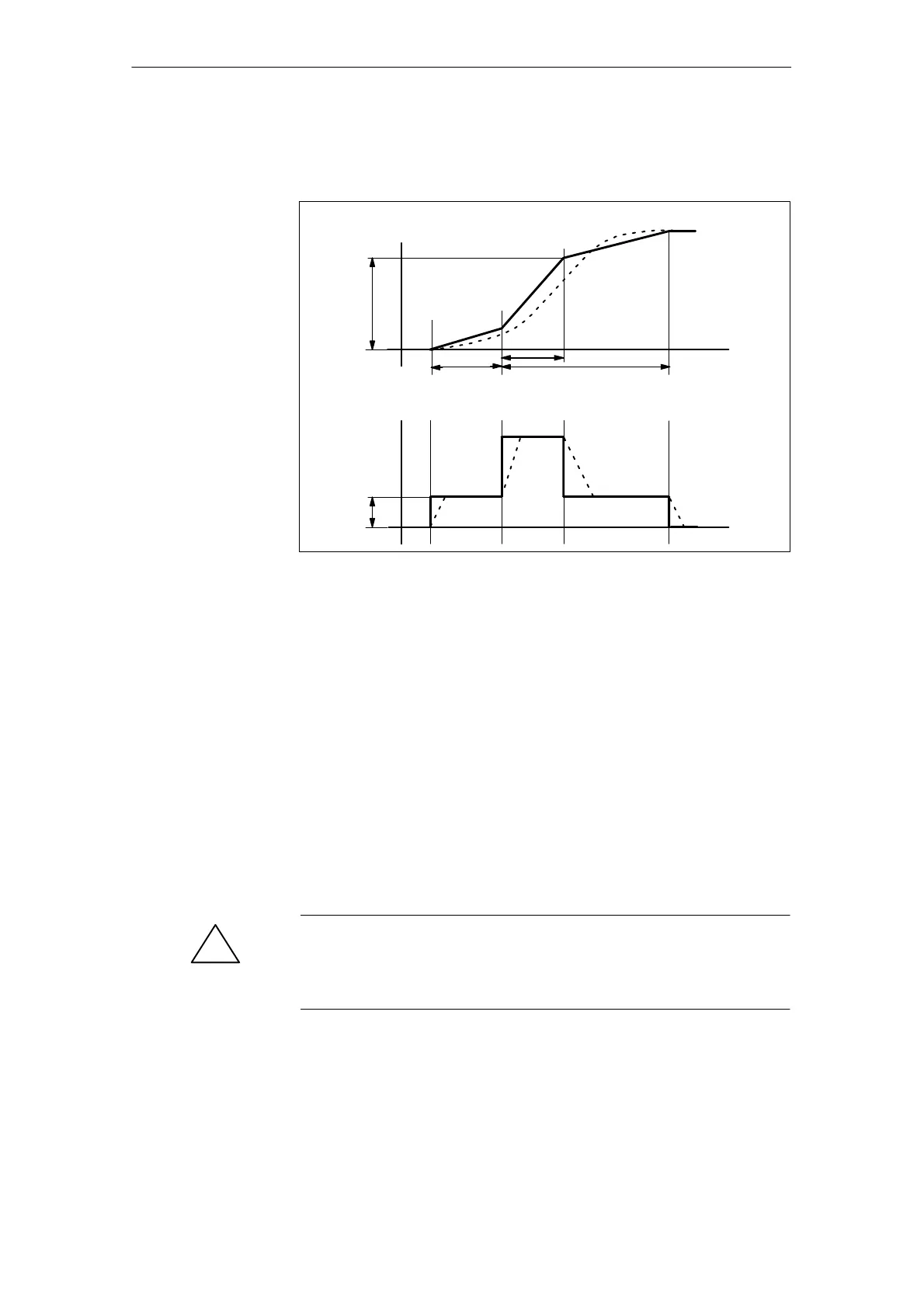
The position setpoint and the actual value of the active measuring system are
recorded.
Speed
Amplitude
Offset
Settling time Measuring duration
t
t
0
0
Position
Ramp
time
Fig. 10-5 Signal curve for the position setpoint/ramp measuring function
At maximum axis velocity, there is a (virtual) step change in the velocity (conti-
nuous line).
The curves represented by the dashed line correspond to a realistic, finite
value. The offset part is calculated from the displayed graph in order to highlight
the transition processes.
To avoid damaging the machine, the step height for the setpoint step change is
limited to the value specified in MD 32000 MAX_AX_VELO. As a result, the
desired step height may not be reached.
The MD 32000 MAX_AX_VELO and MD 32300 MAX_AX_ACCEL have a simi-
lar effect for the setpoint ramp in the ramp area.
The MD 32000 MAX_AX_VELO limits the ramp inclination (speed limit), where-
by the drive does not reach the programmed amplitude.
The restriction in acceleration caused by the MD 32300 MAX_AX_ACCEL
“smoothes” the transition at the start and end of the ramp.
!
Danger
Do not make changes to the MD 32000 MAX_AX_VELO and MD 32300
MAX_AX_ACCEL (e.g. to achieve a certain pitch) without carefully considering
the consequences. These have been matched exactly to the machine!
Step height
10 Drive O
timization

 Loading...


