[diff-sseinphasigl1-020926-rei, 1, en_GB]
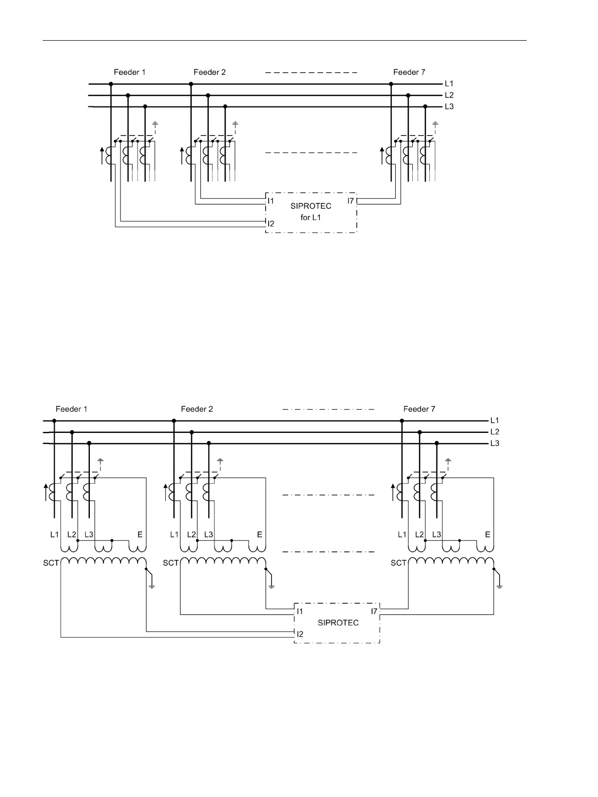
Figure 2-42 Single-phase busbar protection, illustrated L1
Connection via Summation CT
One single device 7UT6x is sufficient for the busbar if the device is connected via summation current trans-
formers. The 3 phase currents of each feeder are converted into single-phase back-up current by means of the
summation CTs. Current summation is unsymmetrical; thus, different sensitivity is valid for different types of
fault. 7UT612 is suited for a busbar with up to 7, 7UT613 and 7UT633 are suited for a busbar with up to 9,
7UT635 for up to 12 feeders.
A common nominal current must be defined for the entire busbar. Matching of the currents can be performed
in the summation transformer connections if the feeder CTs have different nominal currents. The output of
the summation transformers is normally designed for IM = 100 mA at symmetrical rated busbar current. The
nominal current at the device input Ι
N Obj
= 100 mA is applicable.
[diff-ssmischwandler-020926-rei, 1, en_GB]
Figure 2-43 Busbar protection with connection via summation current transformers (SCT)
Different schemes are possible for the connection of the current transformers. The same CT connection
method must be used for all feeders of a busbar.
The scheme as illustrated in Figure 2-44, is the most commonly used. The three input windings of the summa-
tion transformer are connected to the CT currents Ι
L1
, Ι
L3
and Ι
E
. This connection is suitable for all kinds of
Functions
2.2 Differential Protection
112 SIPROTEC 4, 7UT6x, Manual
C53000-G1176-C230-5, Edition 09.2016

 Loading...


