Overexcitation Protection
The overexcitation protection is used to detect increased overflux or overinduction conditions in generators
and transformers, especially in power station unit transformers, which cause impermissible temperature rise
in the iron. An increase in induction above the rated value leads very quickly to saturation of the iron core and
to large eddy current losses which cause impermissible temperature rise in the iron. This protection is not
applicable to single-phase busbar protection.
The overexcitation protection picks up when the permissible limit of induction is exceeded in the core of the
protected object (e.g. power station unit transformer). Increased induction occurs, for example, when the
power station block is disconnected from the system from full-load, and the voltage regulator either does not
operate or does not operate sufficiently fast to control the associated voltage rise. Similarly a decrease in
frequency (speed), e.g. in island systems, can cause increased induction in the transformer.
Functional Description
Measured Values
The use of the overexcitation protection presumes that measured voltages are connected to the device: This is
therefore only possible for 7UT613 and 7UT633. Overexcitation protection makes no sense on 1-phase busbar
protection and is, therefore, not available for this application.
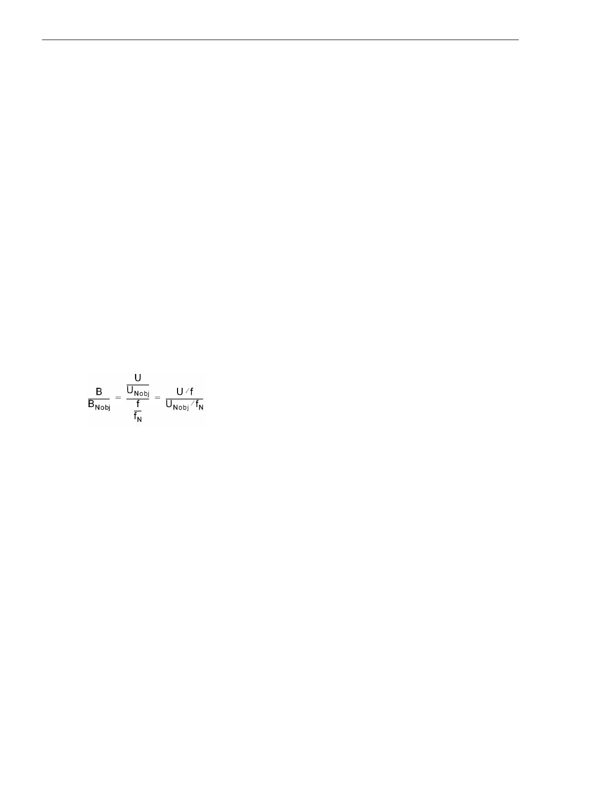
The overexcitation protection measures the ration voltage/frequency U/f, which is proportional to the induc-
tion B in the iron core (with invariable dimensions).
If the quotient U/f is set in relation to the voltage and frequency under nominal conditions of the protected
object U
NObj
/f
N
, a direct measure of the induction B, referred to the induction B/B
NObj
under nominal conditions,
is achieved. All constant quantities cancel each other:
[b-n-obi-030603-st, 1, en_GB]
The benefit of these referred values is that no explicit calculations are necessary. You can enter all values
directly referred to the induction under nominal conditions of the protected object. The device has been
informed about the rated values of the protected object and the voltage transformer data when setting the
object and transformer data.
The maximum of the three phase-to-phase voltages is decisive for the calculation. The voltages are filtered by
numerical algorithms. Monitoring is carried out throughout the frequency tagging range.
Characteristics
The overexcitation protection includes two definite time stages and a further thermal characteristic which
latter forms an approximate replica of the temperature rise caused by overflux in the protected object.
As soon as a threshold (warning stage U/f >) has been exceeded, the pickup indication is output and a timer
T U/f > starts. A warning message is transmitted subsequently to the expiration of this timer. As soon as a
second threshold (warning stage U/f >>) has been exceeded, another pickup indication is output and a timer
T U/f >> starts. A trip command is issued subsequent to the expiration of this timer.
2.11
2.11.1
Functions
2.11 Overexcitation Protection
218 SIPROTEC 4, 7UT6x, Manual
C53000-G1176-C230-5, Edition 09.2016

 Loading...


