[leistungsmessung-am-generator-en, 1, --_--]
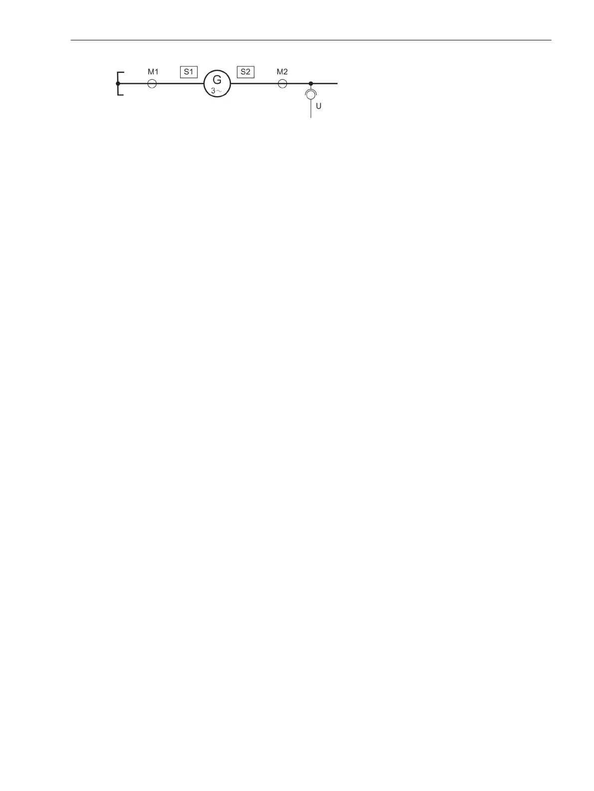
Figure 2-9 Power measurement at generator
If you have the choice to assign a side or a measuring location to the main protected object as shown in
Figure 2-9 (S1 is identical to M1), such assignment of the side is preferable, because the power can be set
later directly in the (mostly known) reference values. As the nominal data of the main protected object are
known to the device, no conversion of reference values to secondary values will be required.
The under- and overvoltage protection and the frequency protection also use the voltages connected to the
device. Select the side or measuring location here, which is electrically connected to the voltage transformer
set.
Should the voltages not be required for the protection functions, select the voltages that must be indicated or
transferred as operational measured values during operation, or on the basis of which you wish to calculate
the power.
For the 1-phase voltage measurement input U4, likewise a side or measuring location can be selected at
address 262 VT U4 - irrespective of the assignment of the 3-phase voltage inputs. This measuring input is
frequently used for the displacement voltage, measured at the e-n windings of the voltage transformer set,
but you can also use it for detection of any other measured voltage. In this case set VT U4 = conn/not
assig. (connected, but not assigned). If no voltage is needed at the 1-phase voltage input, set Not
connected (not connected).
As different connections are possible, you must now specify in the device how the connected 1-phase voltage
should be interpreted. This is done at address 263 VT U4 TYPE. Set Udelta transf. if the voltage
assigned acc. to address 262 is a displacement voltage. It can also be any phase-to-earth voltage (e.g. UL1E
transform.), or a phase-to-phase voltage (e.g. UL12 transform.). If U4 is connected to a voltage which
is assigned to no side or measuring location, set Ux transformer.
General Power System Data
General
The device requires some plant and power system data in order to be able to adapt its functions accordingly,
dependent on the actual application. The data required include for instance rated data of the substation and
the measuring transformers, polarity and connection of the measured quantities, if necessary features of the
circuit breakers, and others. There are also certain parameters common to all functions, i.e. not associated
with a specific protection, control or monitoring function. These data can only be changed from a PC running
DIGSI and are discussed in this section.
Rated Frequency
The rated frequency of the power system is set under address 270 Rated Frequency. The available rated
frequencies are 50 Hz, 60 Hz and 16,7 Hz (7UT613/63x).
Phase Sequence
Under address 271 PHASE SEQ. the presetting for clockwise rotation L1 L2 L3 can be changed if a power
plant has an anticlockwise rotation L1 L3 L2. The phase sequence has no influence on the vector group
conversion of the differential protection as long as the identical phase rotation is present on all sides of the
protected object. This setting is irrelevant for single-phase application and is not accessible.
2.1.4.2
Functions
2.1 General
SIPROTEC 4, 7UT6x, Manual 55
C53000-G1176-C230-5, Edition 09.2016
 Loading...


