In practice, the voltage assignment depends therefore on the voltages which the device is expected to receive
and process. Of course, voltage transformers must be installed at the appropriate locations and connected to
the device.
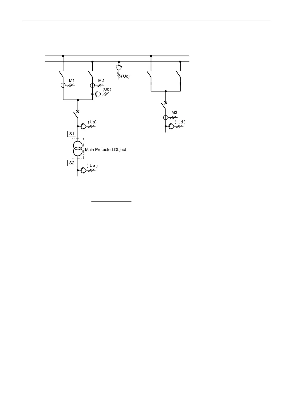
[beispiel-spannungszuordung-270503-st, 1, en_GB]
Figure 2-8 Examples of measured voltage assignment
Voltage assignment:
Ua Voltage is measured at side S1 of the main protected object (power transformer)
Ub Voltage is measured at the measuring location M2, assigned to side 1 of the main
protected object
Uc Voltage is measured at a busbar
Ud Voltage is measured at the non-assigned measuring location M3
Ue Voltage is measured at side S2 of the main protected object (power transformer)
If the voltage transformers represented as Ua do not exist in your system, you can, for instance, use the
voltages at Measuring loc.2 (represented as Ub), as they are electrically identical (assuming that the
circuit breaker is closed). The device then assigns the voltage automatically to side 1 and calculates the power
of the side from this voltage and the current of side S1, which is the sum of the currents from the measuring
locations M1 and M2.
If no voltages are connected, set Not connected.
If the overflux protection function is used, you must choose (and connect) a voltage that is suitable for over-
flux protection. For transformers it must be a non-regulated side, since a proportional relationship between
the quotient U/f and the iron core induction B is found only there. If, for example in Figure 2-8, the winding at
side 1 has a voltage controller, Side 2 must be selected.
For the power protection functions it is important that the voltages are measured at such locations where the
currents are flowing from which the power will be calculated. If, for example, the power is relevant that is
flowing from the high-voltage side (side S1) into the transformer, as shown in Figure 2-8, the assignment is
set at address 261 VT SET = Side 1. At the measuring locations M1 and M2 the flowing currents are multi-
plied by the voltage at Ua, in order to obtain the power.
In case of reverse power protection for a generator, the currents are usually measured in the starpoint leads
and the voltages at the terminal side (Figure 2-9). It is also advisable here to not to assign the voltage to meas-
uring location M2 or to side S2, but to measuring location M1 or to side S1. For the power calculation the
voltages at U with currents at M1 are taken into consideration. It is thus ensured that the active power supply
of the generator from the network is evaluated as reverse power.
Functions
2.1 General
54 SIPROTEC 4, 7UT6x, Manual
C53000-G1176-C230-5, Edition 09.2016

 Loading...


