Checking Connections
Checking Data Connections of Interfaces
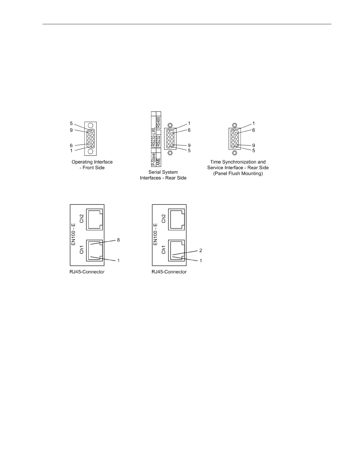
Pin assignments
The following tables illustrate the pin assignment of the various serial device interfaces and of the time
synchronisation interface and the Ethernet interface. The position of the connections can be seen in the
following figure
[dsub-buchsen-020313-kn, 1, en_GB]
Figure 3-27 9-pin D-subminiature female connectors
[rj45-buchse-20070404, 1, en_GB]
Figure 3-28 RJ45 sockets
Operator interface
When the recommended communication cable is used, correct connection between the SIPROTEC 4 device
and the PC is automatically ensured. See the Appendix for an ordering description of the cable.
Service interface
Check the data connection if the service interface (Interface C) for communicating with the device is via fix
wiring or a modem. If the service port is used as input for one or two RTD-boxes, verify the interconnection
according to one of the connection examples given in the Appendix C Connection Examples zu überprüfen.
System interface
When a serial interface of the device is connected to a central substation control system, the data connection
must be checked. The visual check of the assignment of the transmission and reception channels is of partic-
ular importance. With RS232 and fibre optic interfaces, each connection is dedicated to one transmission
direction. Therefore the output of one device must be connected to the input of the other device and vice
versa.
With data cables, the connections are designated according to DIN 66020 and ISO 2110:
•
TxD = Data output
•
RxD = Data input
3.2
3.2.1
Mounting and Commissioning
3.2 Checking Connections
SIPROTEC 4, 7UT6x, Manual 349
C53000-G1176-C230-5, Edition 09.2016

 Loading...


