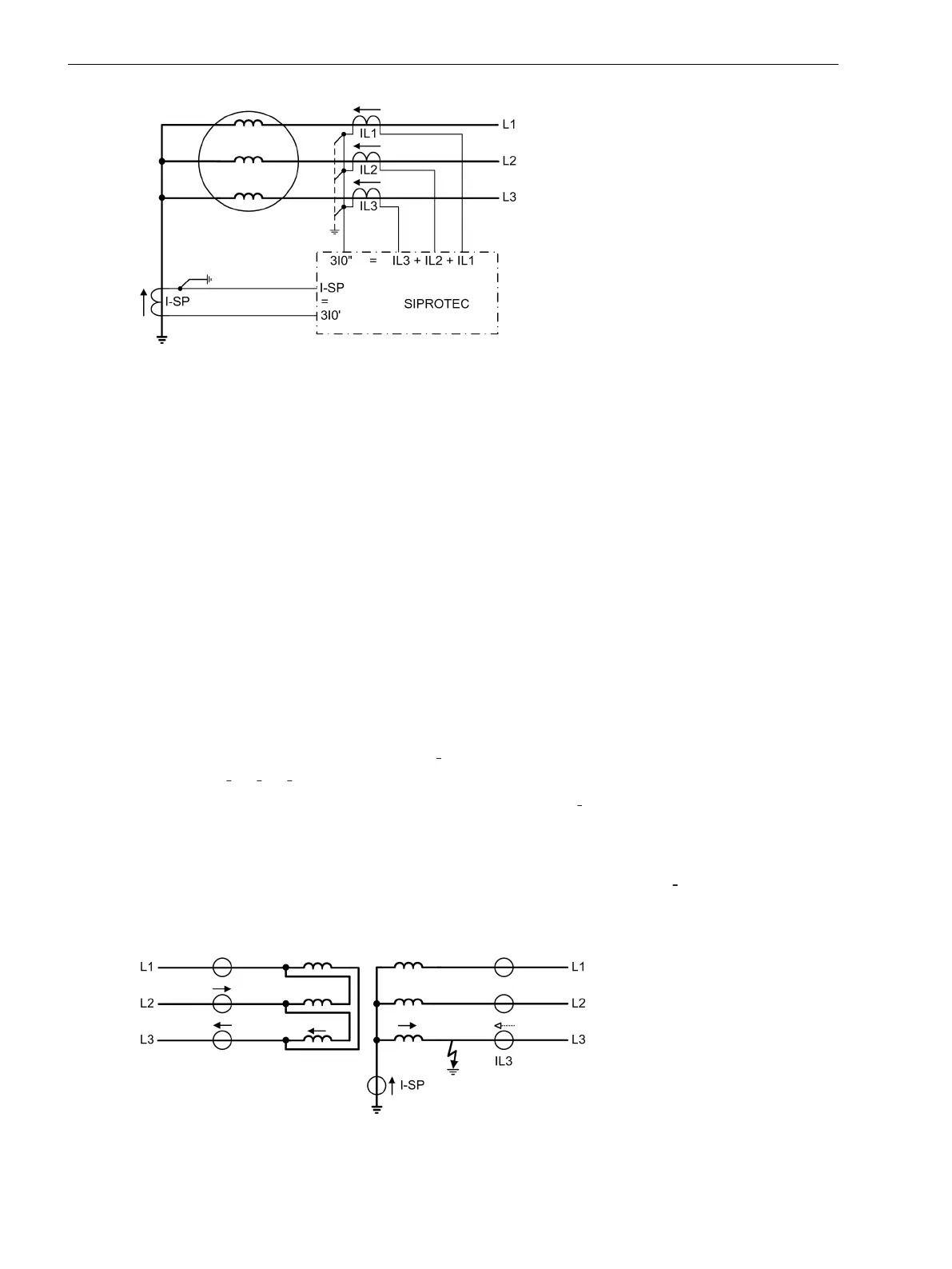
[erddiff-prinzip-an-generator-mit-geer-sternpkt-020926-st, 1, en_GB]
Figure 2-58 Restricted earth fault protection on a generator or motor with earthed starpoint
The restricted earth fault protection can operate on one of the sides of the main protected object (power
transformer, generator, motor, reactor) or on a further protected object, according to the topology config-
ured. In case of auto-transformers, it is assigned to the auto-windings. Furthermore, it is presumed that the
assignment of the different measuring locations to the sides of the main protected object or to a further
protected object as well as the assignment of the 1-phase current input for the starpoint current has been
performed correctly according to the Section 2.1.4.1 Topology of the Protected Object.
The 7UT613/63x provides two of the protective functions that can be used independently from each other in
different locations. For example you can realise a restricted earth fault protection for each of both windings on
a YNyn transformer that is earthed at both starpoints. Or use the first restricted earth fault protection for an
earthed winding of a transformer and the second for another protected object, e.g. a neutral reactor. You
carried out the assignment of both restricted earth fault protection functions to the sides or measuring loca-
tions according the Section 2.1.4.3 Assignment of Protection Functions to Measuring Locations / Sides vorge-
nommen.
Function Description
Measuring Principle
During healthy operation, no starpoint current
Ι
Ctrl
flows through the starpoint lead. The sum of the phase
currents 3Ι
0
=Ι
L1
+ Ι
L2
+ Ι
L3
is almost zero.
When an earth fault occurs in the protected zone, a starpoint current Ι
Ctrl
will flow; depending on the earthing
conditions of the power system a further earth current may be recognised in the residual current path of the
phase current transformers (dashed arrow in Figure 2-59), which is, however, more or less in phase with the
starpoint current. All currents which flow into the protected zone are defined positive.
Bei einem Erdkurzschluss im Schutzbereich fließt auf jeden Fall ein Sternpunktstrom
Ι
St
; je nach den Erdungs-
verhältnissen des Netzes kann auch über die Leiterstromwandler ein Erdstrom auf die Fehlerstelle speisen
(gestrichelter Pfeil im Figure 2-59), der jedoch mehr oder weniger in Phase mit dem Sternpunktstrom ist.
Dabei ist die Stromrichtung in das Schutzobjekt als positiv definiert.
[erddiff-erdkurzschluss-innerhalb-020926-rei, 1, en_GB]
Figure 2-59 Example for an earth fault in a transformer with current distribution
2.3.2
Functions
2.3 Restricted Earth Fault Protection
128 SIPROTEC 4, 7UT6x, Manual
C53000-G1176-C230-5, Edition 09.2016
 Loading...


