[logikdia-unterspannungsschutz, 1, en_GB]
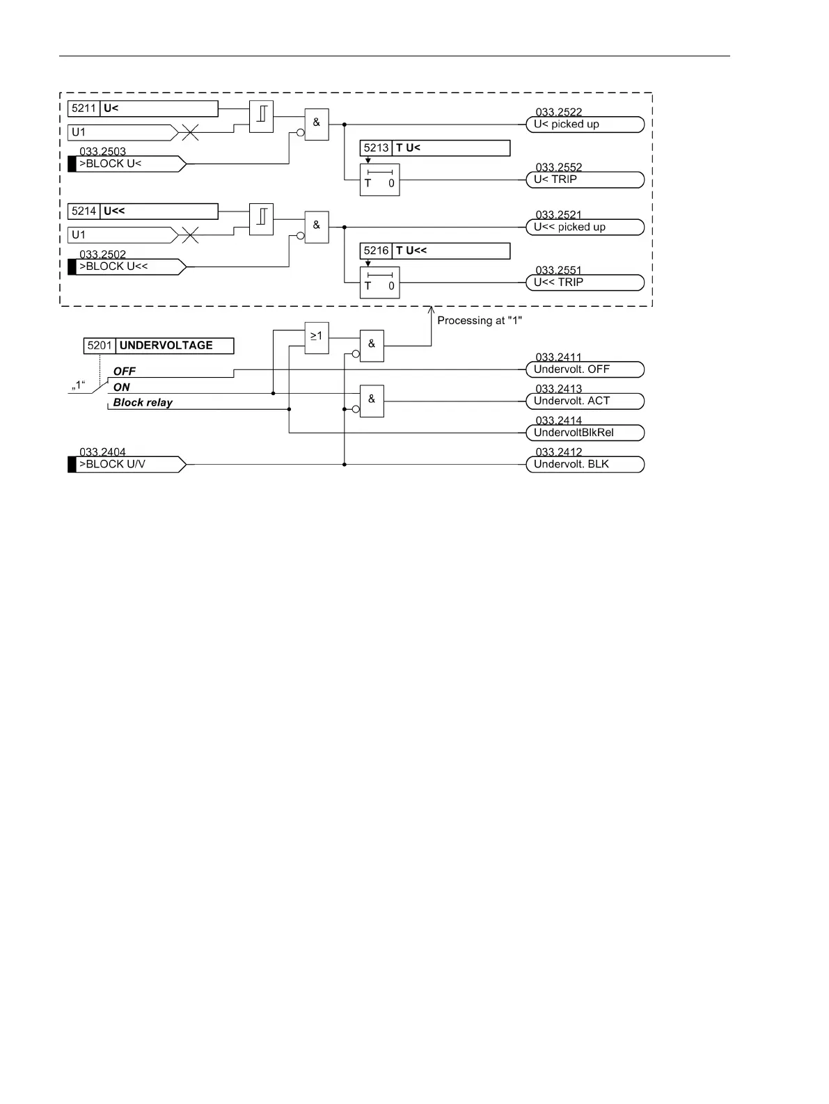
Figure 2-106
Logic diagram of the undervoltage protection
Setting Notes
General
The application of undervoltage protection is only possible in 3-phase protected objects. Furthermore, it is a
prerequisite that the device is connected to a three-phase voltage transformer set.
Undervoltage protection is only effective and accessible if address 152 UNDERVOLTAGE was set to Enabled
during configuration of the protection function (Section 2.1.3 Functional Scope).
At address 5201 UNDERVOLTAGE the undervoltage protection ON or OFF can be set. Additionally, the
command can be blocked if the protection function is enabled (Block relay).
Pickup Values, Times
The undervoltage protection consists of two phases. The equivalent of the phase-phase voltage is detected,
therefore √3 · U
1
. The setting is thus effected in interlinked values.
The U< stage is set slightly below the minimum operational expected voltage under address 5212 U<, if the
reference values are relevant, under address 5211 U< when setting in volts. This setting method depends on
whether the voltage transformer set has been assigned to one side of the main protected object or to any
measuring location. Normally, 75 % to 80 % of the nominal voltage is recommended; i.e. 0.75 to 0.80 for
reference values or 75 V to 80 V for U
N sec
= 100 V (adjusted accordingly in case of different nominal voltage).
The respective delay time T U< (address 5213) is supposed to bridge the permissible short-term voltage dips
during continuous undervoltage, which may lead to an unstable operation, however, it is supposed to be
switched off within a few seconds.
For the U<< stage, a lower pickup threshold with a short delay should be set so that in case of heavy voltage
dips a quick trip can occur, e.g. 65 % of the nominal voltage with 0.5 s delay.
If the undervoltage protection is assigned to one side of the main protected object or the three-phase busbar,
the pickup value must be set as reference value under address 5215 U<<, e.g. 0.65. When assigned to a meas-
uring location, the value of phase-phase voltage must be set under address 5214 U<<, e.g. 71.5. V at U
N sec
=
110 V (65 % of 110 V).
2.14.2
Functions
2.14 Undervoltage Protection
234 SIPROTEC 4, 7UT6x, Manual
C53000-G1176-C230-5, Edition 09.2016
 Loading...


