[ausloeselogik-1be-bsp-ausloesekreis1-121102-st, 1, en_GB]
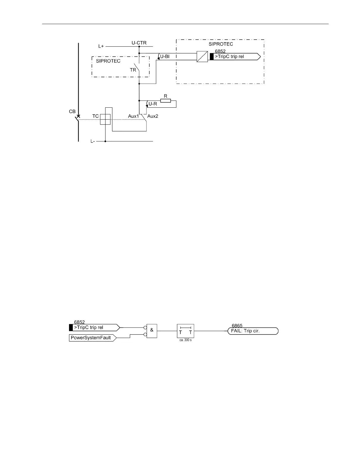
Figure 2-120 Logic diagram of the trip circuit supervision using one binary input
TR Trip relay contact
CB Circuit breaker
TC Circuit breaker trip coil
Aux1 Circuit breaker auxiliary contact (make)
Aux2 Circuit breaker auxiliary contact (break)
U-CTR Control voltage (trip voltage)
U-BI Input voltage of binary input
U-R Voltage across the substitute resistor
R Bypass resistor
During normal operation, the binary input is activated (logical condition “H”) when the trip contact is open and
the trip circuit is intact, because the supervision circuit is closed either by the circuit breaker auxiliary contact
(if the circuit breaker is closed) or through the equivalent resistor R. Only as long as the trip contact of the
command relay is closed, the binary input is short-circuited and thereby deactivated (logical condition “L”).
If the binary input is permanently deactivated during operation, an interruption in the trip circuit or a failure of
the (trip) control voltage can be assumed.
The trip circuit supervision does not operate during system faults. A momentary closed tripping contact does
not lead to a failure indication. If, however, the trip contacts of other devices are connected in parallel, the
alarm must be delayed.
When the fault in the trip circuit has been cleared, the annunciation is automatically reset.
[ausloesekreisueb-mit-1be-121102-st, 1, en_GB]
Figure 2-121 Logic Diagram of the Trip Circuit Supervision with One Binary Input (simplified)
Setting Notes
During configuration of the scope of functions, the number of binary inputs per trip circuit was set at address
182 Trip Cir. Sup. (see 2.1.3.1 Setting Notes).
If the allocation of the required binary inputs does not match the selected monitoring mode, a message to
that effect appears (
TripC ProgFail
).
The trip circuit supervision can be switched at address 8201 TRIP Circuit Supervision ON or OFF.
2.19.2.2
Functions
2.19 Monitoring Functions
SIPROTEC 4, 7UT6x, Manual 261
C53000-G1176-C230-5, Edition 09.2016
 Loading...


