TR Trip relay contact
CB Circuit breaker
TC Circuit breaker trip coil
Aux1 Circuit breaker auxiliary contact (make)
Aux2 Circuit breaker auxiliary contact (break)
U-CTR Control voltage (trip voltage)
U-BI1 Input voltage of 1st binary input
U-BI2 Input voltage of 2nd binary input
The diagram shows the circuit breaker in closed state.
Depending on the state of the trip relay and the circuit breaker s auxiliary contacts, the binary inputs are trig-
gered (logical state “H” in the following table) or short-circuited (logical state and “L”).
The state where both binary inputs are not activated (“L”), is only possible during a short transition phase in
intact trip circuits (command relay has issued trip command, but the CB has not yet opened).
A continuous state of this condition is only possible when the trip circuit has been interrupted, a short-circuit
exists in the trip circuit, or battery voltage failure occurs. It is thus used as a monitoring criterion.
Table 2-11 Status table of the binary inputs depending on command relay and circuit breaker switching
state
No. Trip relay
contact
Circuit breaker Aux.1 Aux.2 BI 1 BI 2
1 open ON closed open H L
2 open OFF open closed H H
3 closed ON closed open L L
4 closed OFF open closed L H
The conditions of the two binary inputs are checked periodically. A query takes place about every 500 ms.
Only after n = 3 of these consecutive state queries have detected a fault, an alarm is given. The repeated
measurements determine the delay of the alarm message and avoid that an alarm is output during short tran-
sition periods. After the fault in the trip circuit is removed, the alarm is reset automatically after the same
time.
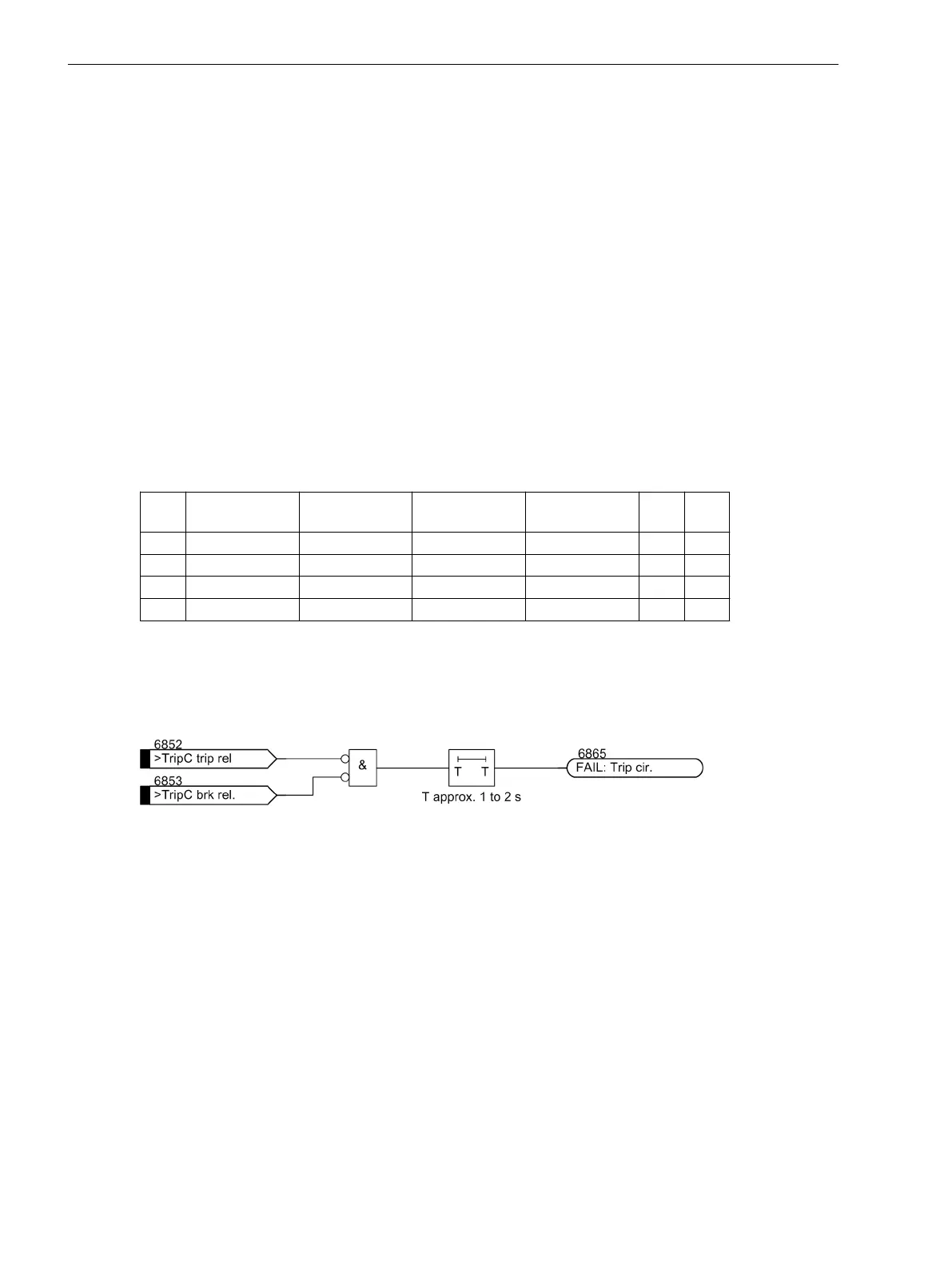
[ausloeselogik-mit-2be-121102-st, 1, en_GB]
Figure 2-119 Logic Diagram of the Trip Circuit Supervision with Two Binary Inputs (simplified)
Supervision Using One Binary Input
The binary input is connected in parallel to the respective command relay contact of the protection device
according to Figure 2-120. The circuit breaker auxiliary contact is bridged with the help of a high-ohmic substi-
tute resistor R.
The control voltage for the circuit breaker should be at least double the size of the minimum voltage drops at
the binary input (U
Ctr
> 2 · U
BImin
). Since at least 19 V are needed for the binary input, the monitor can be used
with a system control voltage of over 38 V.
An calculation example for the substitute resistance of R is shown in the Section “Mounting and Commis-
sioning”.
Functions
2.19 Monitoring Functions
260 SIPROTEC 4, 7UT6x, Manual
C53000-G1176-C230-5, Edition 09.2016
 Loading...


