[logikdia-erdfehlerdiffentialschutzes-121102-st, 1, en_GB]
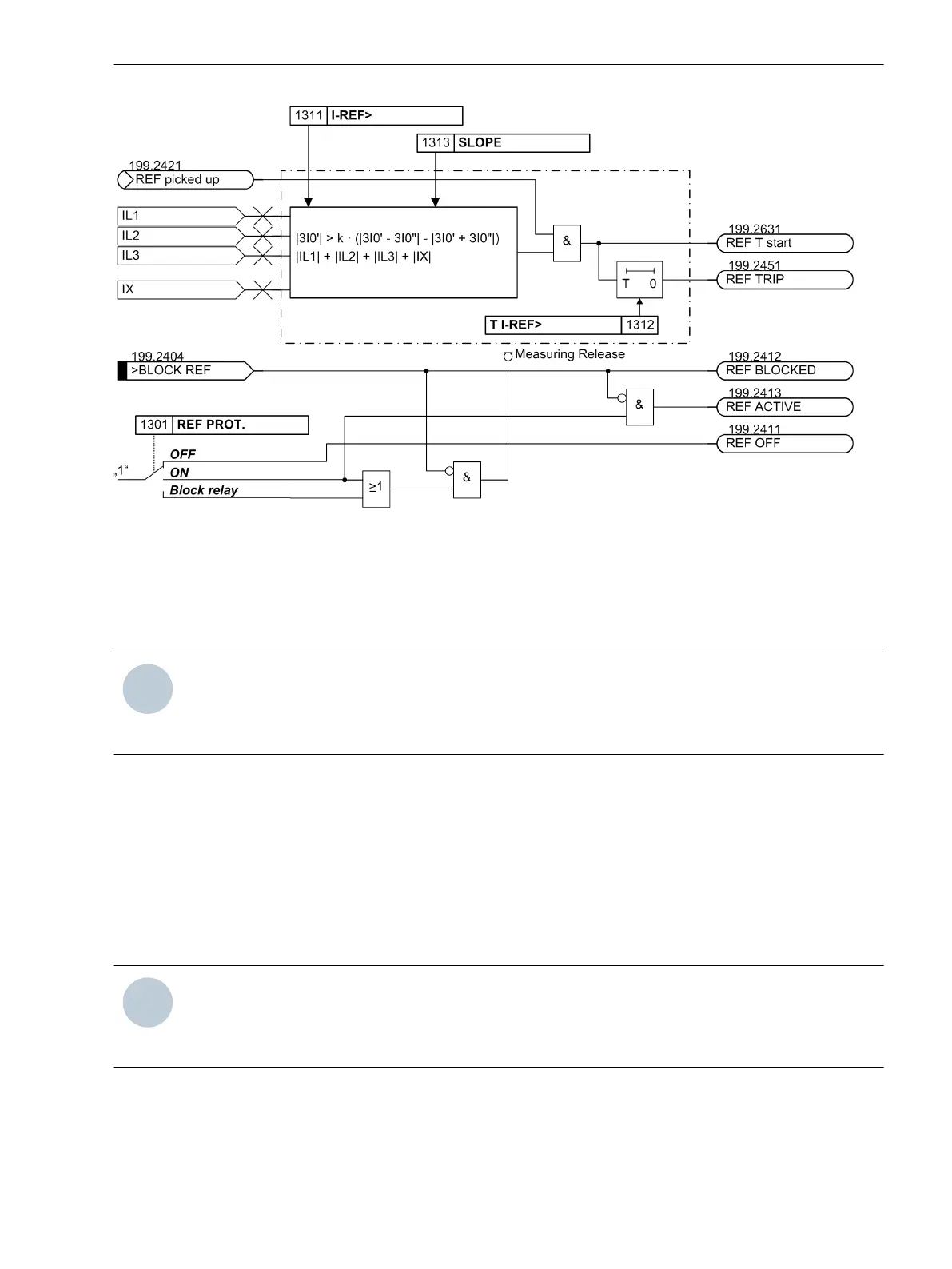
Figure 2-66 Logic diagram of the earth fault protection (simplified)
Setting Notes
General
NOTE
The first restricted earth fault protection is described in the setting instructions. The parameter addresses
and message numbers of the second restricted earth fault protection are described at the end of the setting
instructions under “Additional Restricted Earth Fault Protection Functions”.
The restricted earth fault protection can only operate if this function has been set during configuration of the
functional scope (section 2.1.4 Power System Data 1) under address 113 REF PROT. to Enabled. If the
second restricted earth fault protection is used, it also needs to be set at address 114 REF PROT. 2 to
Enabled. Furthermore, a further 1-phase measured current input must be assigned to the same side or meas-
uring location where the starpoint current is to be processed (see Section 2.1.4 Power System Data 1, margin
heading “Assignment of Auxiliary 1-phase Measuring Locations”). The restricted earth fault protection itself
must have been assigned to this side or measuring location (see Section 2.1.4 Power System Data 1, margin
heading “Restricted Earth Fault Protection”.
The first restricted earth fault protection can be set at address 1301 REF PROT. to enabled (ON) or disabled
(OFF); when set to Block relay, the protection function operates but no trip command is issued.
NOTE
When delivered from factory, the restricted earth fault protection is switched OFF. The reason is that the
protection must not be in operation unless at least the assigned side and CT polarity have been properly set
before. Without proper settings, the device may show unexpected reactions (incl. tripping)!
The sensitivity of the protection is determined by I-REF> setting (address 1311). This is the earth fault
current which flows through the starpoint lead of the protected object (transformer, generator, motor, shunt
reactor). A further earth current which may be supplied from the network does not influence the sensitivity.
The setting value refers to the rated current of the protected side of the main protected object or, in case of a
further protected object, to the rated operation current of the corresponding measuring location.
2.3.3
Functions
2.3 Restricted Earth Fault Protection
SIPROTEC 4, 7UT6x, Manual 133
C53000-G1176-C230-5, Edition 09.2016
 Loading...


