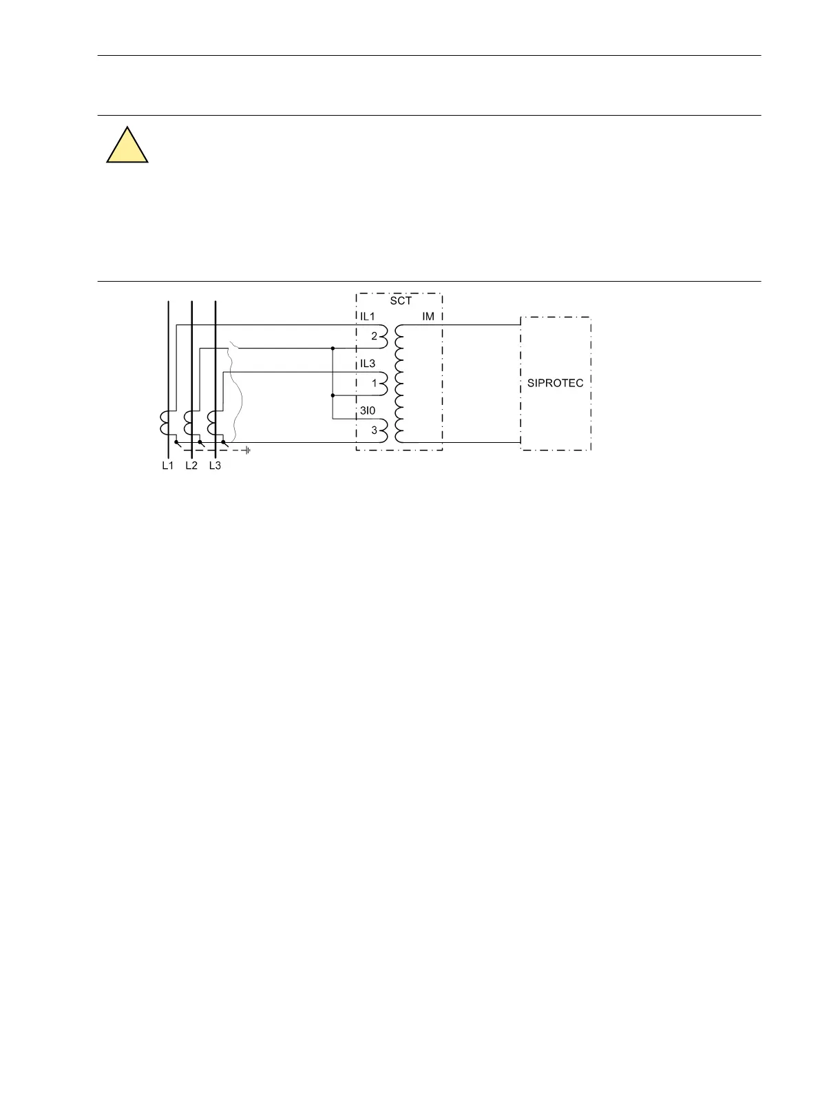
Therefore the current transformer of phase L2 is short-circuited as shown in Figure 3-45
DANGER
Manipulations on the measuring current transformers must be performed with the utmost precau-
tion!
Non-observance of the following measures will result in death, severe personal injury or substantial
property damage.
²
Short-circuit the current transformers before disconnecting any current supply leads to the device!
[mischwandlerl1l3e-unsym-7ut612-021026-rei, 1, en_GB]
Figure 3-45 Asymmetrical test with summation transformer connection L1-L3-E
The measured current is now 2.65 times the current of the symmetrical test.
This test must be carried out for each summation CT.
Testing of the Non-Assigned 1-Phase Current Inputs
As far as single-phase current inputs belong to the main protected object, i.e. they are assigned to a side of
the main protected object, they were already checked with the zero sequence current tests.
Even if they are not assigned to the main protected object but to a 3-phase measuring location of a further
protected object (e.g. restricted earth fault protection for a separate neutral earthing reactor), the same proce-
dure as for the zero sequence current applies. Perform the zero sequence current tests unless it has already
been done.
Single-phase measured current inputs of the device can also be used for any desired 1-phase protection func-
tion. If this is an actual case and the same input has not yet been checked as a starpoint current input of the
main protected object, an additional check of this 1-phase input must be carried out.
The test methods depend widely on the application of the single-phase input.
By any means, the matching factors for the magnitude have to be checked (address 712, 713 etc. depending
on the input under test; refer also to Section 2.1.4 Power System Data 1 under margin heading “Current Trans-
former Data for 1-phase Auxiliary Current Inputs”). Consider whether or not the input under test is a high-
sensitivity input (address 255 for Ι
X3
or 256 for Ι
X4
, refer to Section 2.1.4 Power System Data 1 under margin
heading “High-Sensitivity Auxiliary 1-phase Measuring Locations”). Where applicable, consider the matching
factors (addresses 734 and 744 respectively) when reading out the current magnitudes.
Polarity check is not required since only the current magnitude is processed.
With high-impedance protection the assigned 1-phase current corresponds to the fault current in the
protected object. Polarity of all current transformers supplying the resistor whose current is measured must be
uniform. For this purpose, traversing currents are used as for differential protection checks. Each current trans-
former must be included into a measurement. The measured current must not exceed, for each through-
current test, half of the pickup value of the single-phase time overcurrent protection.
3.3.11
Mounting and Commissioning
3.3 Commissioning
SIPROTEC 4, 7UT6x, Manual 385
C53000-G1176-C230-5, Edition 09.2016

 Loading...


