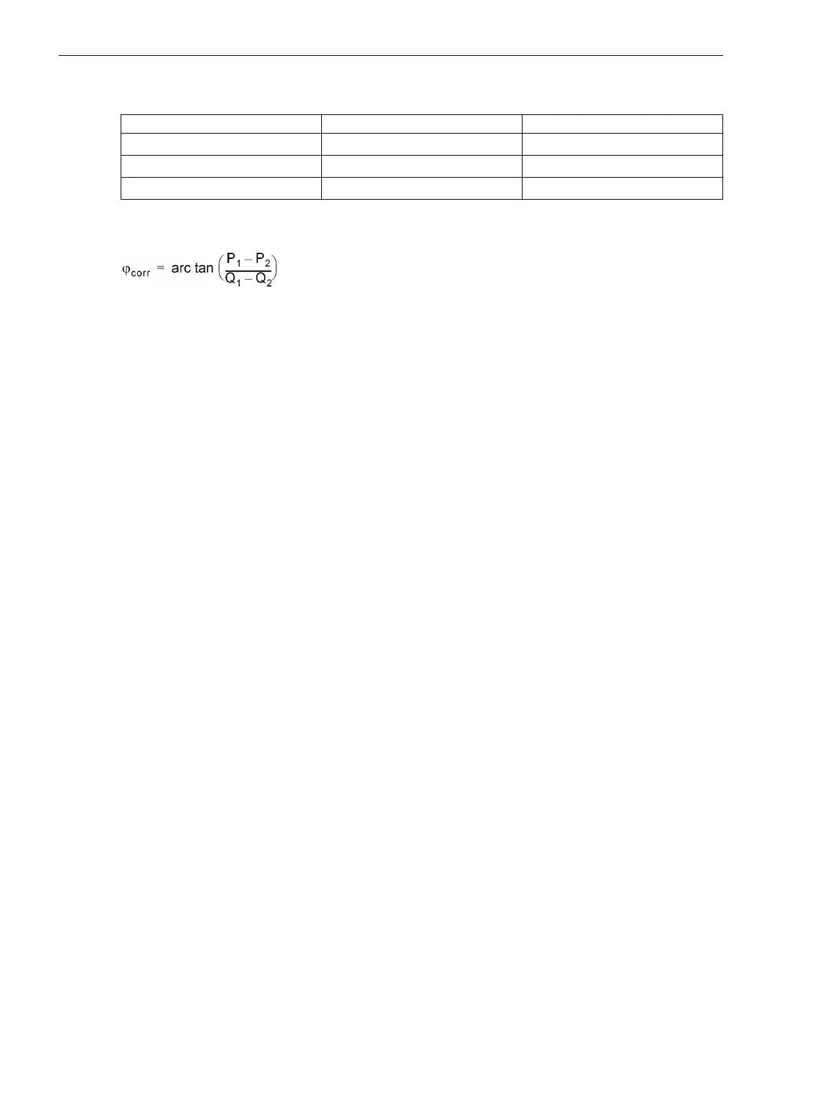
Table 3-34 Motoring and reactive power for angle correction of the transformer error
State Motoring Energy Reactive Power
1
P
0
Q
0
2
P
1
Q
1
3
P
2
Q
2
The read-out measured values P1 and P2 are now used to carry out CT angle error correction: First calculate a
correction angle from the measured value pairs according to the following formula:
[winkelkorrekturwandlerfehler, 1, en_GB]
The power values must be inserted with their correct polarity as read out! Otherwise faulty result!
This angle φ
corr
is entered with reversed sign as the new correction angle under address 803 CORRECT. U
Ang:
Setting Value CORRECT. U Ang = – φ
corr
Reverse Power Protection Setting for Generator
If an exact reverse power protection is used on a generator, you can now calculate the optimum setting value.
If a generator is connected with the network, reverse power can be caused by
•
closing of the regulating valves,
•
closing of the stop valve.
For the first case, the motoring power has already been determined from the prescribed measurements. As
the pickup value of the reverse power protection corresponds to approximately half the motoring power, set
the pickup value of the reverse power protection P> REVERSE in address 5011 (in Watt) or 5012 (referred to
the nominal current of the generator) to a quarter of the sum of the read-out measured values P
1
and P
2
– also
with negative sign –.
Because of possible leakages in the valves, the reverse power test should be performed with emergency trip-
ping.
•
Start up generator and synchronise with network, if not yet done.
•
Close stop valve.
•
From the operational measured value for the active power, the motoring power measured with the
protection device can be derived.
•
If that value should be found to be unexpectedly less than the reverse power with the stop valves closed,
50% of that value should be taken as the setting for the reverse power protection.
•
Re-open stop valve.
•
Shut down the generator.
Testing User-defined Functions
The device has a vast capability for allowing functions to be defined by the user, especially with the CFC logic.
Any special function or logic added to the device must be checked.
A general procedure cannot in the nature of things be specified. Configuration of these functions and the set
value conditions must be actually known beforehand and tested. Especially, possible interlocking conditions of
the switching devices (circuit breakers, isolators, grounding electrodes) must be observed and checked.
3.3.13
Mounting and Commissioning
3.3 Commissioning
390 SIPROTEC 4, 7UT6x, Manual
C53000-G1176-C230-5, Edition 09.2016
 Loading...


