•
Start up generator and synchronize with network. During exact synchronous working, active and reactive
power are theoretically zero.
•
Reduce driving power to zero by closing the regulating valves. The generator now takes motoring energy
from the network.
CAUTION
For a turbine set, the intake of reverse power is only permissible for a short time, since operation of the
turbine without a certain throughput of steam (cooling effect) can lead to overheating of the turbine
blades!
²
•
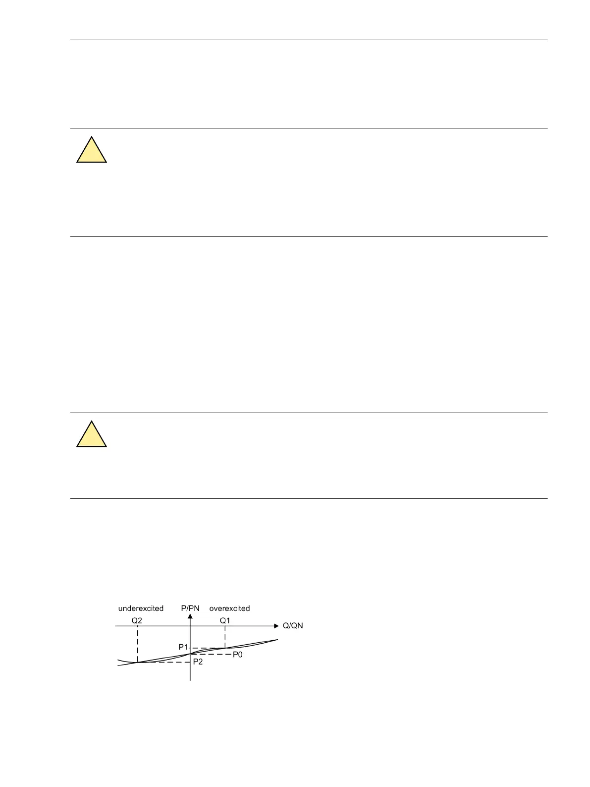
Adjust excitation until the reactive power amounts to approximately Q = 0. To check this, read the active
and reactive power including sign (negative) in the operational measured values and note it down as P
0
(see table below). Read the reactive power with sign in the operational measured values and note it
down as Q
0
(see table below).
•
Slowly increase excitation to 30 % of rated apparent power of generator (overexcited).
– Read the motoring power P
1
with polarity (negative sign) in the operational measured values under
and write it down (see figure below).
– Read out the reactive power Q
1
with polarity (positive sign) and write it down (see table in the figure
below).
•
If possible reduce excitation to approximately 0.3 times rated apparent power of generator (underex-
cited).
CAUTION
Under-excitation may cause the generator fall out of step!
²
•
Read the motoring power P
2
with polarity (negative sign) in the operational measured values under and
write it down (see Table 3-34).
– Read the reactive power Q
2
with polarity (negative sign) in the operational measured values and
write it down (see Table 3-34) .
•
Adjust generator to no-load excitation and shut down if applicable (if not, follow the next margin
heading).
[ermittlung-korrekturwinkel, 1, en_GB]
Figure 3-48 Determination of the correction angle φ
corr
Mounting and Commissioning
3.3 Commissioning
SIPROTEC 4, 7UT6x, Manual 389
C53000-G1176-C230-5, Edition 09.2016
 Loading...


