[logik-schalterversagerschutz-einfach-040603-st, 1, en_GB]
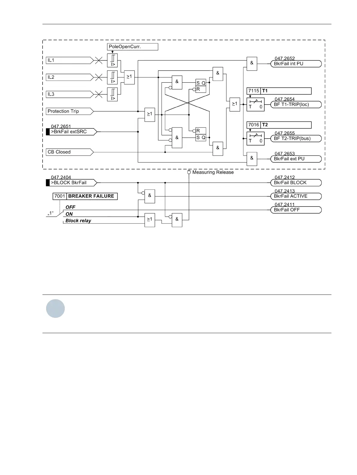
Figure 2-111
Logic diagram of the breaker failure protection (simplified)
Indication numbers and indication designations refer to the first circuit-breaker failure protection.
Setting Notes
General
NOTE
The first circuit breaker failure protection is described in the setting instructions. The parameter addresses
and message numbers of the second circuit breaker failure protection are described at the end of the
setting instructions under “Additional Circuit Breaker Failure Protection Functions”.
The circuit-breaker failure protection is only effective and accessible if address 170 BREAKER FAILURE is set
to Enabled during configuration. In case of single-phase busbar protection no circuit-breaker failure protec-
tion is possible.
If the second circuit-breaker failure protection is used, this must be set under address 171 BREAKER FAIL. 2
to Enabled.
When assigning the protection functions (Section 2.1.4.3 Assignment of Protection Functions to Measuring
Locations / Sides under margin heading “Further 3- phase Protection Functions”, it was determined under
address 470 BREAKER FAIL.AT at which side or measuring location of the protected the circuit-breaker
failure protection must be active. Please ensure that the side or measuring location of the current and the
monitored circuit breaker belong together! Both must be at the supply side of the protected object.
For the second circuit-breaker failure protection the respective address 471 BREAKER FAIL2AT applies
At address 7001 BREAKER FAILURE the first circuit-breaker failure protection ON or OFF is set. The option
Block relay allows to operate the protection but the trip output relay is blocked.
2.17.2
Functions
2.17 Circuit Breaker Failure Protection
SIPROTEC 4, 7UT6x, Manual 247
C53000-G1176-C230-5, Edition 09.2016
 Loading...


