[diff-trafo-einpasen-erdkurzschluss-020926-rei, 1, en_GB]
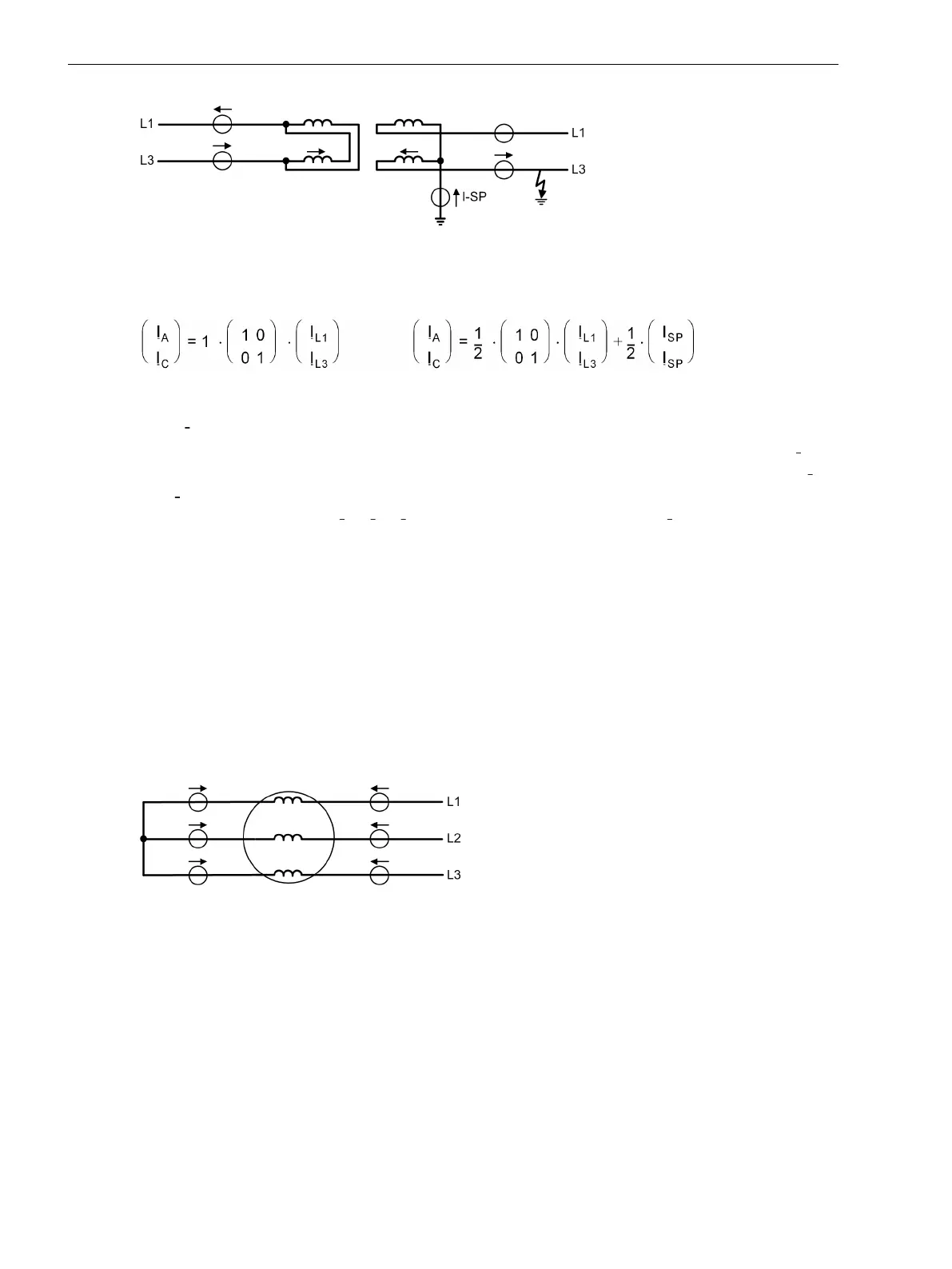
Figure 2-35 Example of an earth fault outside a single-phase transformer with current distribution
The matrix equation in this cases is as follows:
[diff-trafo-gleich-einph-sternpunkt-021026-rei, 1, en_GB]
Where
Ι
SP
is the current measured in the “starpoint” connection.
The zero sequence current is not eliminated. Instead of this, for each phase half of the starpoint current
Ι
SP
is
added. The effect is that the zero sequence current is considered in case of an internal ground fault (from Ι
0
=
–
1
/
2
·
Ι
SP
), whilst the zero sequence current is eliminated in case of an external fault because the zero sequence
current on the terminal side 2 · Ι
0
= (Ι
L1
+ Ι
L3
) compensates for the starpoint current Ι
SP
. Almost full sensitivity
(with zero sequence current) is thus achieved for internal earth faults and full elimination of the zero
sequence current in case of external earth faults.
Even higher earth fault sensitivity during internal earth fault is possible by means of the restricted earth fault
protection (Section 2.3 Restricted Earth Fault Protection) erreichen.
Differential Protection for Generators, Motors, and Series Reactors
Matching of the Measured Values
Equal conditions apply for generators, motors, and series reactors. The protected zone is limited by the sets of
current transformers at each side of the protected object. On generators and motors, the CT are installed in
starpoint connection at the terminal side. Since the current direction is normally defined as positive in the
direction of the protected object, for differential protection schemes, the definitions shown in Figure 2-36.
[diff-generator-laengsdiff-020926-rei, 1, en_GB]
Figure 2-36 Definition of current direction with longitudinal differential protection
The differential protection in 7UT6x refers all currents to the rated current of the protected object. The device
is informed about the rated machine data during setting: the rated apparent power, the rated voltage, and the
rated currents of the current transformers. Measured value matching is therefore reduced to magnitude
factors.
Transverse Differential Protection
The use as transverse differential protection involves a special point. For this application, the definition of the
current direction is shown in Figure 2-37.
For transverse differential protection, the phases connected in parallel constitute the border between the
protected zone and the network. A differential current appears in this case only, but always, if there is a
current difference within the particular parallel phases, so that a fault current in one phase can be assumed.
2.2.3
Functions
2.2 Differential Protection
108 SIPROTEC 4, 7UT6x, Manual
C53000-G1176-C230-5, Edition 09.2016

 Loading...


