Use on Single-phase Auto-transformers
Single-phase transformers can be designed with one or two windings per side; in the latter case, the winding
phases can be wound on one or two iron cores. In order to ensure that optimum matching of the currents
would be possible, always two measured current inputs shall be used even if only one current transformer is
installed on one phase. The currents are to be connected to the inputs Ι
L1
and Ι
L3
of the device, they are desig-
nated Ι
L1
and Ι
L3
in the following.
If two winding phases are available, they may be connected either in series (which corresponds to a wye-
winding) or in parallel (which corresponds to a delta-winding). The phase displacement between the windings
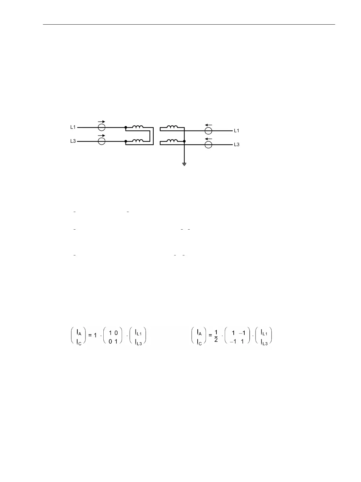
can only be 0° or 180°. Figure 2-34 shows an example of a single-phase power transformer with two phases
per side with the definition of the direction of the currents.
[diff-trafo-einpasen-020926-rei, 1, en_GB]
Figure 2-34 Example of a single-phase transformer with current definition
Like with 3-phase power transformers, the currents are matched by programmed coefficient matrices which
simulate the difference currents in the transformer windings. The common form of these equations is:
(
Ι
m
) = k· (K)· (Ι
n
)
with
(Ι
m
) - matrix of the matched currents Ι
A
, Ι
C
,
k - constant factor for magnitude matching,
(K) - coefficient matrix,
(Ι
n
) - matrix of the phase currents Ι
L1
, Ι
L3
.
Since the phase displacement between the windings can only be 0° or 180°, matching is relevant only with
respect to the treatment of the zero sequence current (besides magnitude matching). If a “Starpoint” of the
protected transformer winding is not earthed (left in Figure 2-34), the phase currents can directly be used.
If the “starpoint” is earthed (figure Figure 2-34 right side), the zero sequence current must be eliminated
unless it can be compensated by considering the “Starpoint current”. By eliminating the zero sequence current,
fault currents which flow through the transformer during earth faults in the network in case of an earth point
in the protected zone (transformer starpoint) are rendered harmless without any special external measures.
The matrices for the left and the right winding as per Figure 2-34 are
[diff-trafo-gleich-einph-nullstromelim-021026-rei, 1, en_GB]
The disadvantage of elimination of the zero sequence current is that the differential protection becomes less
sensitive (by factor
1
/
2
because the zero sequence current amounts to
1
/
2
in case of an earth faults in the
protected zone). Higher earth fault sensitivity can be achieved if the “starpoint” current is available, i.e. if a CT
is installed in the “starpoint” connection to earth and this current is fed to the device (Figure 2-35). For consid-
eration of the earth fault current, the advanced parameter diff protection with measured earth current, side x
must be switched on (addresses 1211DIFFw.IE1-MEAS bis 1215DIFFw.IE5-MEAS = YES).
Functions
2.2 Differential Protection
SIPROTEC 4, 7UT6x, Manual 107
C53000-G1176-C230-5, Edition 09.2016

 Loading...


